HSD
5801H0056 ______________________________________________________________ 170/181
Procedure for S1
After replacing the sensor as described in paragraph 8.8.12, calibrate it as follows:
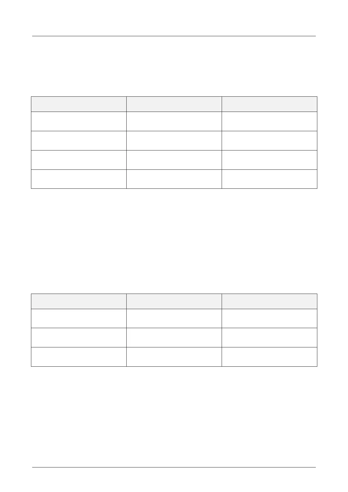
1. Use the gauge of 14.29mm and the thickness spacer of 0.04mm, as shown in Figure 8.18 and
Figure 8.19, and check that the signal supplied by sensor S1 corresponds to that described in
the following table:
CONDITION
THICKNESS SPACER
INTERPOSED
S1 OUTPUT
Gauge blocked
(tool-holder blocked)
YES
HIGH (+24V)
Gauge blocked
(tool-holder blocked)
NO
LOW (0V)
Gauge missing
(tool-holder missing)
-
LOW (0V)
Collet open
(tool-holder expelled)
-
LOW (0V)
2. Rotate the shaft manually and check that the conditions of the table are satisfied for all 360° of
the rotation.
3. If this is not the case, rotate the bush (4) until you find the position that permits you to have the
output described in the above-mentioned table, then definitively tighten the screw (6).
4. Check the effectiveness of the adjustment by performing the maximum possible number of
tests with all the tool-holders available.
Procedure for S4
After replacing the sensor as described in paragraph 8.8.12, calibrate it as follows:
1. Use the gauge of 14.13mm and the thickness spacers of 0.12 and 0.16mm, as shown in
Figure 8.18 and Figure 8.19, and check that the signal supplied by sensor S4 corresponds to
that described in the following table:
CONDITION
THICKNESS SPACER
INTERPOSED
S1 OUTPUT
Gauge blocked
(tool-holder blocked)
0.12mm HIGH (+24V)
Gauge blocked
(tool-holder blocked)
0.16mm LOW (0V)
Collet open
(tool-holder expelled)
- LOW (0V)
2. Rotate the shaft manually and check that the conditions of the table are satisfied for all 360° of
the rotation.
3. If this is not the case, rotate the bush (4) until you find the position that permits you to have the
output described in the above-mentioned table, then definitively tighten the screw (6).
4. Check the effectiveness of the adjustment by performing the maximum possible number of
tests with all the tool-holders available.