HSD
5801H0056 _______________________________________________________________ 81/181
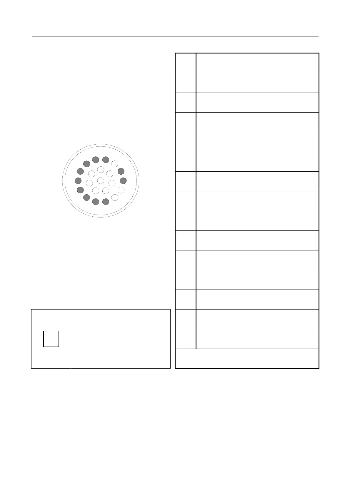
4.6.1.2 Layout of SIGNALS connector (fixed part) - ISO VERSION
PIN DESCRIPTION
1
OUTPUT sensor S2 (collet open).
2
OUTPUT sensor S1
(presence of tool-holder)
3
OUTPUT sensor S3 (shaft stopped)
(optional)
4
+24V CC power supply S1, S2, S3.
5
+24V CC power supply
bulb on the button.
6
0V power supply S1, S2, S3.
7
+24V CC power supply to button
and SC sensor (C-axis zero setting)
8
Button OUTPUT
9
Not used
10
Not used
11
0V power supply
BUTTON, BULB and SC sensor
7
14
1
2
13
15
12
3
16
8
21
22
20
4
17
11
18
5
19
10
6
9
12
SC sensor OUTPUT
(zero setting C-axis)
13
Not used
14
For HSD maintenance.
i
Use 0.35mm
2
cables
or AWG22
From 15 to 22: Not used.