Appearance of the Front Panel
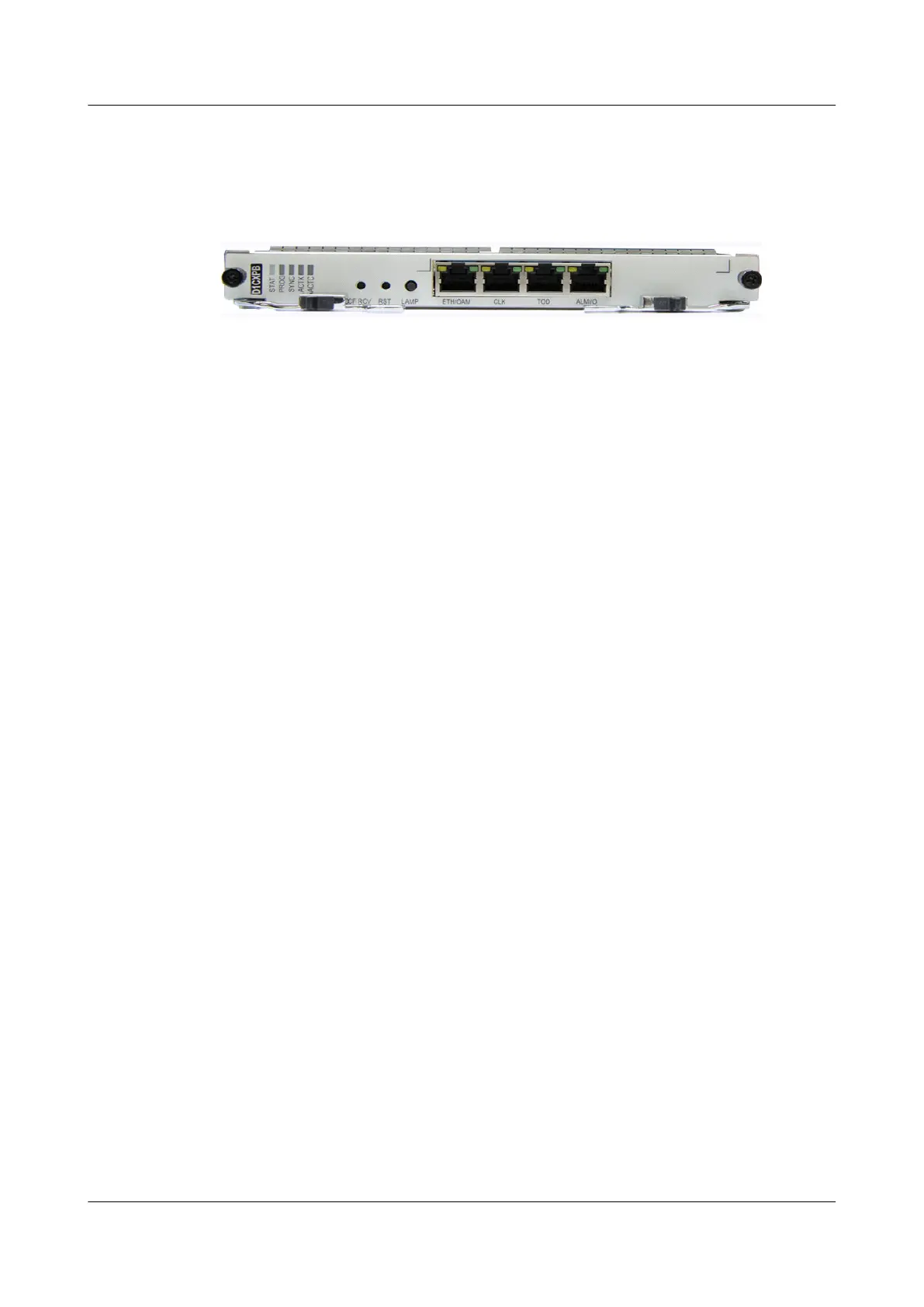
Figure 4-2 shows the appearance of the front panel of the AND1CXPB.
Figure 4-2 Front panel of the AND1CXPB
Indicator
The following indicators are present on the front panel of the AND1CXPB:
l STAT indicator, red, green, or orange, which indicates the working status
l PROG indicator, red or green, which indicates the running status of the program
l SYNC indicator, red or green, which indicates the clock synchronization status
l ACTX indicator, green, which indicates the cross-connection or clock active/standby status
l ACTC indicator, green, which indicates the active/standby system control board
For details on meanings of indicators, see 11 Indicators.
Button
The following buttons are present on the front panel of the AND1CXPB:
l CF RCV button, which is reserved for later use.
l RRST button, which is used for reset on the board. When you press the RST button and
then release it, the board is reset.
l LAMP button, which is used to test the indicators. When you press the LAMP button, all
the board indicators on the NE are on.
Switch for the Ejector Lever
On the front panel, there are two switches for the two ejector levers on the front panel. To remove
a board, you need to push the two switches to the middle and then rotate the ejector levers.
Interface
Table 4-2 lists the types and usage of the interfaces on the AND1CXPB.
ATN 950B Multi-service Access Equipment
Hardware Description
4 AND1CXPA/AND1CXPB - System Control, Cross-
connect, and Multi-protocol Process Unit
Issue 03 (2012-07-23) Huawei Proprietary and Confidential
Copyright © Huawei Technologies Co., Ltd.
30
 Loading...