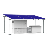
Figure 4-39 Removing the upper cover of the chassis
When removing the upper cover from the chassis, do not use one hand to perform this
operation. Otherwise, the upper cover may collide with the components inside the device,
bringing risks of component damages.
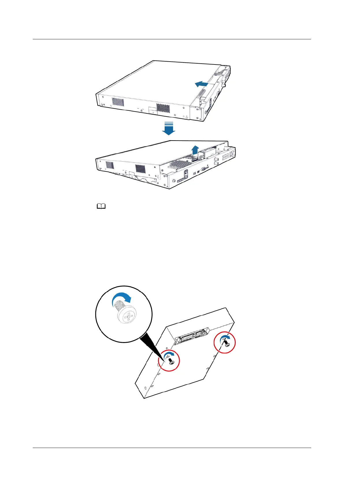
4. Take two #6-32UNC screws from the screw package (there are eight screws in
the package) and preinstall the two screws in the holes near the cable outlet
on the hard disk backplane. Tighten the screw threads for three circles (ensure
that the screws do not fall naturally).
Figure 4-40 Installing disk screws
5. Insert the SATA and power cables into the corresponding ports on the hard
disk. During cable connection, ensure that the metallic plate of the SATA
cable faces upward.
FusionModule500 Smart Mini Data Center
User Manual (Philippines, FusionModule500-
SU61A12S) 4 Installation Guide
Issue 02 (2021-06-30) Copyright © Huawei Technologies Co., Ltd. 85