Table 2-10 RS485 pin denition
Pin Description
1 RS485_T+
2 RS485_T–
3 -
4 RS485_R+
5 RS485_R–
6 GND
7 -
8 -
If cables are prepared onsite, follow the three methods below:
● Connect pin 1 and pin 2. Pin 1 connects to RS485+ and pin 2 connects to RS485–.
● Connect pin 4 and pin 5. Pin 4 connects to RS485+ and pin 5 connects to RS485–.
● Connect pins 1, 2, 4, and 5. Twist cables to pin 1 and pin 4 into one cable and then
connect it to RS485+. Twist cables to pin 2 and pin 5 into one cable and then connect it
to RS485–.
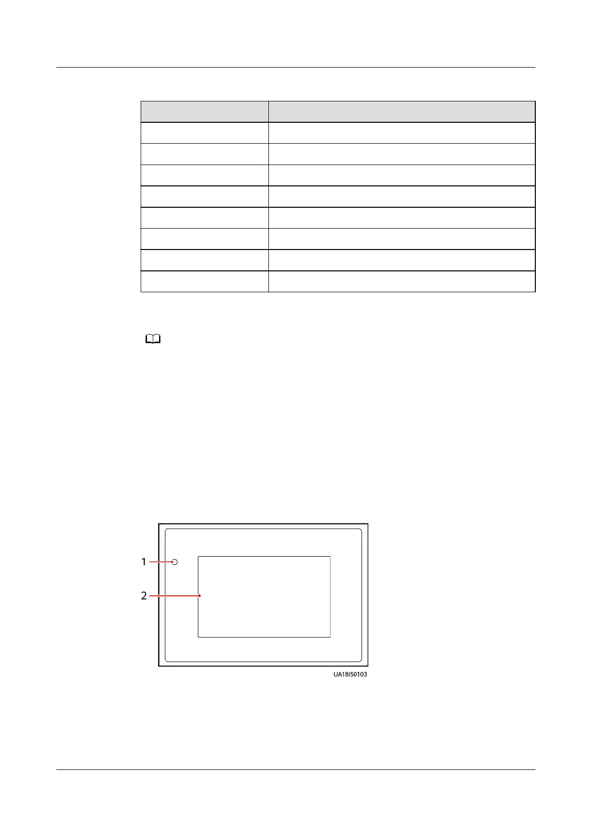
2.3.6 MDU
Appearance
Figure 2-22 MDU
(1) Status indicator
(2) LCD touchscreen
UPS5000-E-(30 kVA–120 kVA)-FM
User Manual 2 Overview
Issue 03 (2022-01-30) Copyright © Huawei Technologies Co., Ltd. 38