optical interface. Then insert the ber into the optical interface, rotate
the outer screw jacket clockwise, and then fasten the optical connector.
– To remove an optical ber, rotate the outer screw jacket counter-
clockwise on the optical interface until the screw loosens. Then gently
pull out the optical ber.
● MPO/PC optical ber connector
Note the following points when removing and inserting an MPO/PC ber
connector:
– When inserting the connector, hold the shell labeled "PUSH" and feed the
male connector into the female connector until you hear a clicking sound.
The male and female connectors are securely installed.
– To disassemble the connector, hold the shell labeled "PULL" and remove
the male connector.
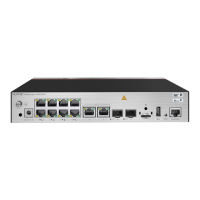
There are four types of optical
bers for the USG6000E: LC/PC-LC/PC, LC/PC-
SC/PC, LC/PC-FC/PC, and MPO/PC-MPO/PC, which are based on the types of
connectors on both ends of the
bers, as listed in Table 4-309.
Table 4-309 Common optical ber types
Type
Transmission
Mode
Connector
On the USG6000E On the peer device
LC/PC-LC/PC Single-mode/
Multi-mode
LC/PC LC/PC
LC/PC-SC/PC SC/PC
LC/PC-FC/PC FC/PC
MPO/PC-
MPO/PC
Multi-mode MPO/PC MPO/PC
HUAWEI USG6000E Series
Hardware Guide 4 Hardware Overview
Issue 08 (2022-04-20) Copyright © Huawei Technologies Co., Ltd. 499
 Loading...