MAXPRO200 Instruction Manual 807700 Revision 1 99
Operation
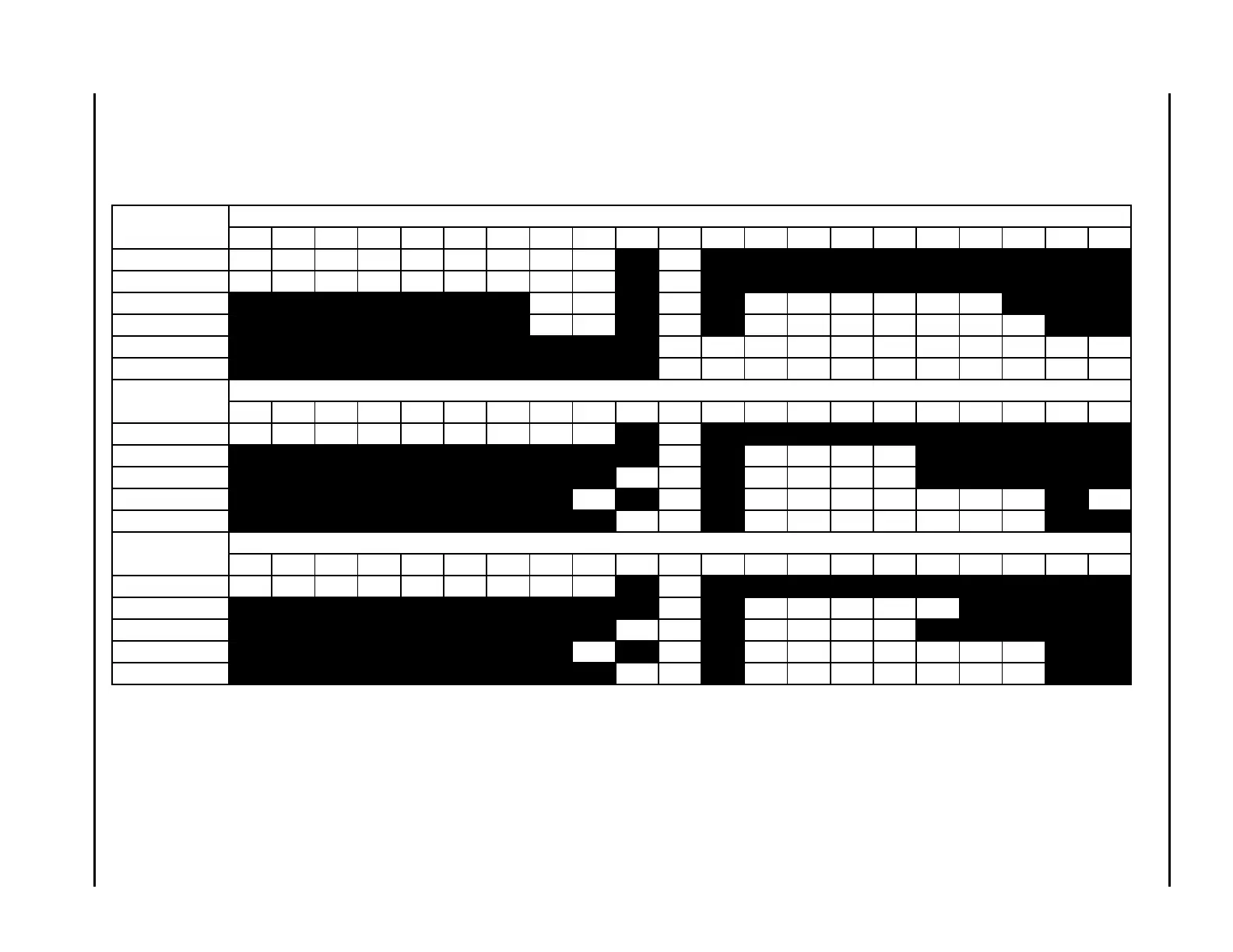
Estimated kerf-width compensation
The kerf widths in the following charts are for reference. Differences between installations and material composition may cause actual results to vary from
those shown in the tables.
Metric
Mild steel
Thickness (mm)
0.50.811.21.522.534568101215202532384450
50A Air / Air 1.72 1.51 1.46 1.52 1.62 1.58 1.53 1.47 1.44 1.57
50A O / Air 1.36 1.35 1.36 1.37 1.39 1.41 1.42 1.44 1.51 1.52
130A Air / Air 2.08 2.21 2.38 2.45 2.48 2.68 3.08 3.46 3.98
130A O / Air 2.29 2.35 2.40 2.56 2.63 2.92 3.45 3.82 4.33 4.78
200A Air / Air 2.68 2.90 2.98 2.95 3.12 3.53 3.98 4.20 4.37 5.02 5.69
200A O / Air 2.55 2.95 3.11 3.04 3.13 3.44 3.96 4.60 5.15 5.77 6.40
Stainless steel
Thickness (mm)
0.50.811.21.522.534568101215202532384450
50A Air / Air 1.45 1.71 1.77 1.68 1.56 1.52 1.50 1.55 1.66
1.71
130A Air / Air 2.57 2.70 2.74 2.90 3.19
130A N / N 2.56 2.40 2.43 2.40 2.59 2.97
200A Air / Air 3.03 2.76 2.76 2.76 2.98 3.35 3.42 3.64 3.85 4.67
200A N / N 3.36 3.20 2.94 2.95 3.32 3.92 3.71 4.22 4.70
Aluminum
Thickness (mm)
0.50.811.21.522.534568101215202532384450
50A Air / Air 1.40 1.40 1.40 1.40 1.40 1.47 1.50 1.52 1.55 1.58
130A Air / Air 2.84 2.80 2.78 2.76 2.77 2.88
130A N / N 2.73 2.57 2.62 2.46 2.61 3.00
200A Air / Air 3.73 3.94 3.44 3.42 3.51 3.73 4.03 4.29 5.38
200A N / N 3.55 3.35 3.04 3.02 3.16 3.52 4.00 4.57 5.04