62 MAXPRO200 Instruction Manual 807700 Revision 1
Installation
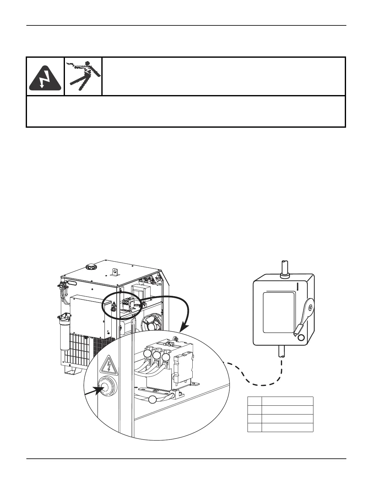
Connect the power
1. Insert the power cable through the strain relief at the rear of the power supply.
2. Connect the ground lead (PE) to the GROUND connector as shown below.
3. Connect the power leads to the contactor terminals as shown below. For models with an EMI filter, connect the
power leads to the EMI filter terminal block. Recommended torque on contactor or EMI filter terminals is 7-8 Nm
(60–70 in-lbs).
4. Verify that the line disconnect switch is in the OFF position and remains in the OFF position for the
remainder of the installation of the system.
5. Connect the power cord leads to the line disconnect switch following national and local electrical codes.
WARNING!
ELECTRIC SHOCK CAN KILL
The line disconnect switch must be in the OFF position before making the power cable connections.
In the U.S., use a “lock-out/tag-out” procedure until installation is complete. In other countries, follow
appropriate national and local safety procedures.
North American wire colors European wire colors
U = Black U = Black
V = White V = Blue
W = Red W = Brown
(PE) Earth ground = Green/yellow (PE) Earth ground = Green/yellow