42 MAXPRO200 Instruction Manual 807700 Revision 1
Installation
Placement of system components
• Place all system components in position prior to making electrical, gas, and interface connections.
Use the diagram in this section for component-placement guidelines.
• Ground all system components to earth. See Recommended grounding and shielding practices on
page 44 for details.
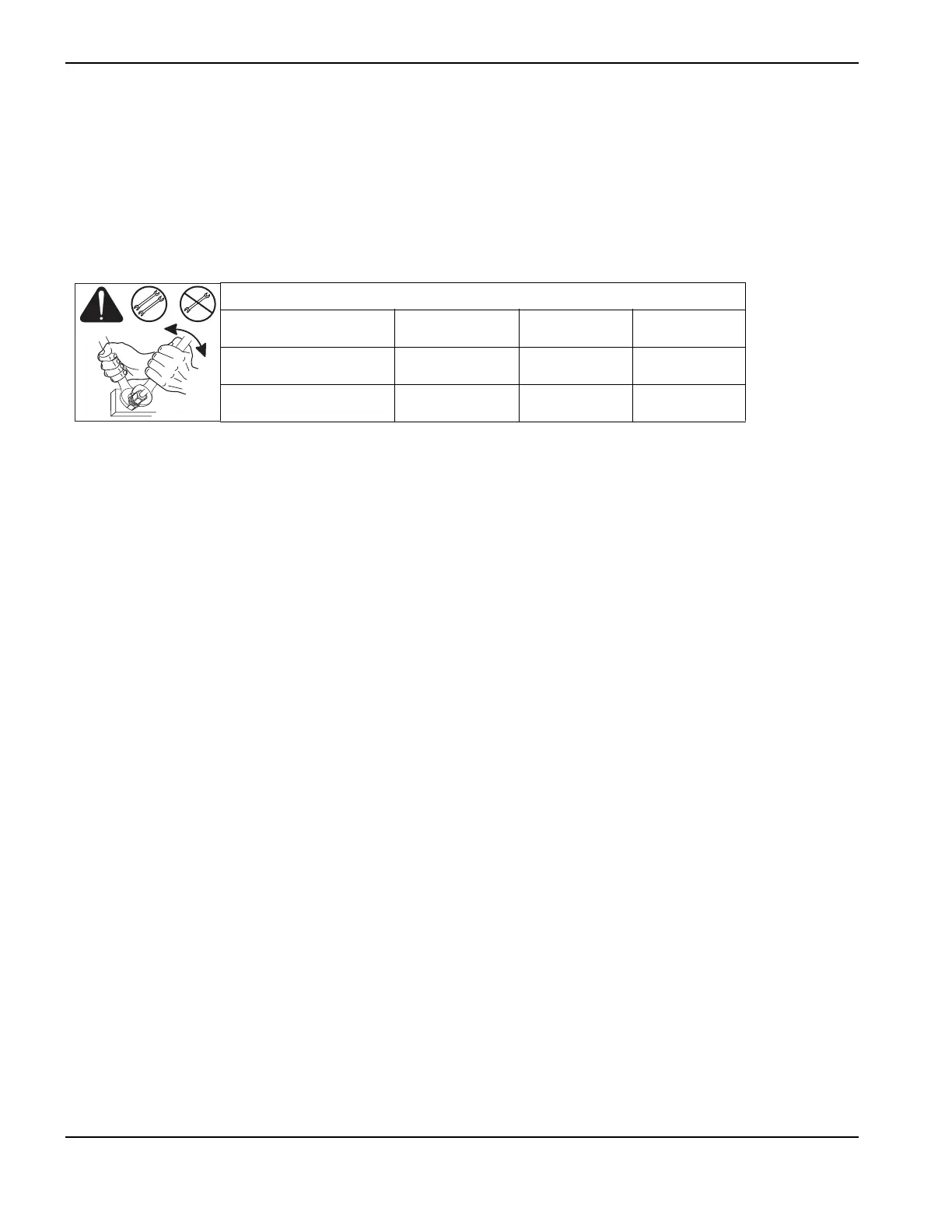
• To prevent leaks in the system, tighten all gas connections as shown below.
Torque specifications
Gas or water hose size kgf-cm lbf-in lbf-ft
Up to 10 mm (3/8 in) 8.9–9.8 75–85 6.25–7
12 mm (1/2 in) 41.5–55 360–480 30–40