44
/
2. Wiring
2.4.4 Connection of PIO
Conduct the connection of I/O to the controller is to be carried out using the dedicated I/O cable. The
cable length is shown in the model code of the controller. Please check the controller model code.
There are 2m for standard, 3m and 5m as an option. 10m is also applicable at maximum if purchased
separately. [Refer to “1.1.5. How to read the model]
Also, the end of the cable harness to be connected to the host controller (PLC, etc.) is just cut and no
treatment is conducted so the wiring layout can be performed freely.
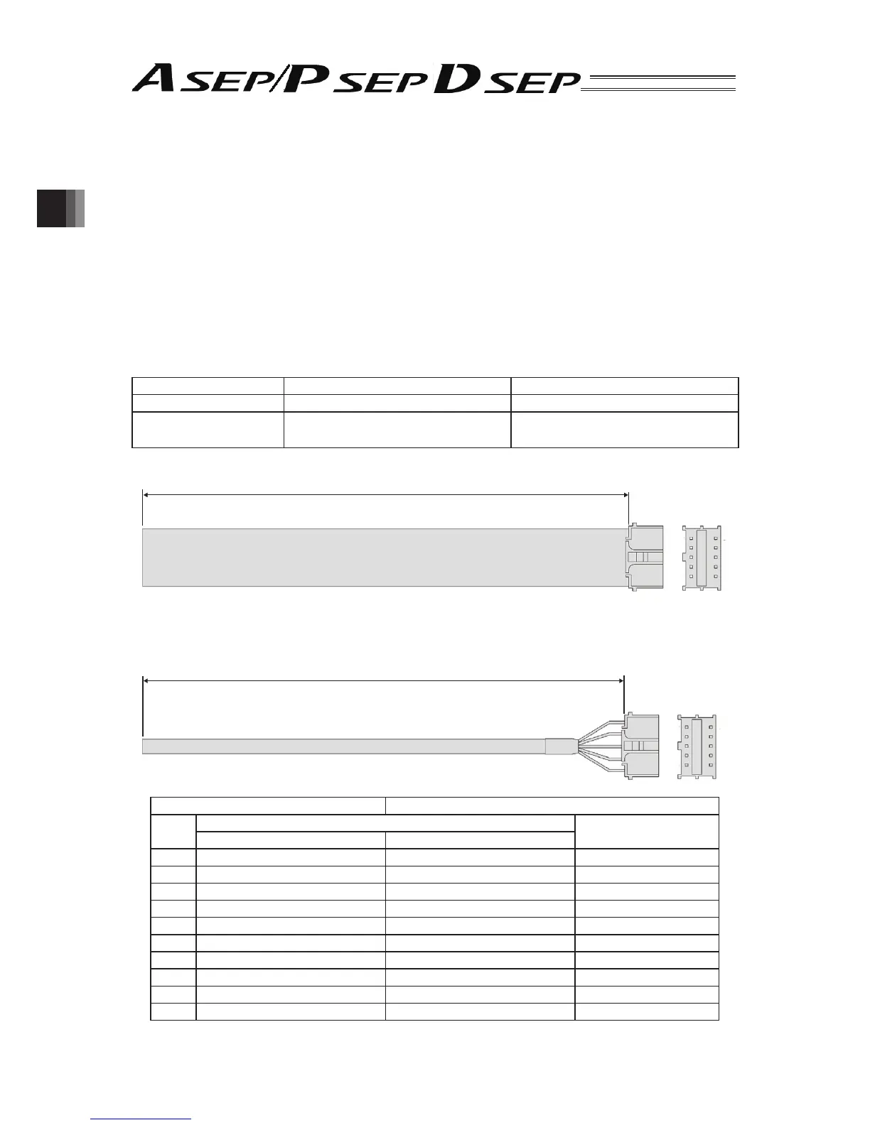
Model : CB-APSEP-PIO□□□···For ASEP-C, PSEP-C
(□□□ shows the cable length L Example.020
2m)
● PIO Connector
Applied Connector 55959-1030 Manufactured by MOLEX
Connector Name I/O PIO Connector
Connection Cable
Dedicated Cable [refer to (3) in this
section.]
Enclosed in this controller
L
10
2 1
9
Model : CB-APSEPW-PIO□□□···For ASEP-CW, PSEP-CW
(□□□ shows the cable length L Example.020
2m)
L
10
21
9
Connector 51353-1000 (Manufactured by MOLEX)
No.
Color
Signal Name
CB-APSEP-PIO□□□ CB-APSEPW-PIO□□□
1 BR BR 24V
2 RD BR, WT 0V
3 OR RD IN0
4 YW RD, WT IN1
5 GN YW IN2
6 BL YW, WT IN3
7 PL GN OUT0
8 GY GN, WT OUT1
9 WT BK OUT2
10 BK BK, WT OUT3