35
/
2. Wiring
2.3 Circuit Diagram (Example)
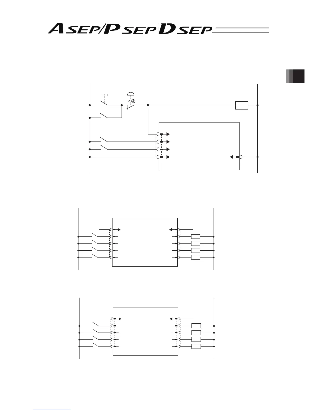
[1] Power/Emergency Stop Circuit
CR
CR
CR
Brake Power Sopply
Motor Power Sopply
ASEP/PSEP/DSEP
Emergency
Stop Release
Switch
24V 0V
EMG (Emergency Stop Input)
BK
(BK connection not required for DSEP)
MP
24V 0V
Emergency
Stop Switch
for Device
(System)
Power Supply Connector
Turn ON to
Release Brake
[2] Pattern 0 : Point-to-Point Movement (Standard)
1) Single Solenoid System
ASEP/PSEP/DSEP
PIO Connector
Movement Signal
Pause Signal
(Reset Signal)
Servo ON Signal
0V (NPN Type)
24V DC (PNP Type)
BR
OR
YW
GN
BL
1
3
4
5
6
RD
PL
GY
WT
BK
2
7
8
9
10
P24
ST0
*STP
RES
–/SON
0V
LS0/PE0
LS1/PE1
HEND/SV
*ALM/SV
24V DC (NPN Type)
0V (PNP Type)
Backward Position Detection/
Backward Positioning Completion
Forward Position Detection/
Forward Positioning Completion
Home Return Completion/
Servo ON Signal
Alarm Output Signal/
Servo ON Signal
Load
24V DC
Supply
0V Supply
2) Double Solenoid System
ASEP/PSEP/DSEP
PIO Connector
Backward Position
Movement Signal
Forward Position
Movement Signal
(Reset Signal)
Servo ON Signal
0V (NPN Type)
24V DC (PNP Type)
BR
OR
YW
GN
BL
1
3
4
5
6
RD
PL
GY
WT
BK
2
7
8
9
10
P24
ST0
*STP
RES
–/SON
0V
LS0/PE0
LS1/PE1
HEND/SV
*ALM/SV
24V DC (NPN Type)
0V (PNP Type)
Backward Position Detection/
Backward Positioning Completion
Forward Position Detection/
Forward Positioning Completion
Home Return Completion/
Servo ON Signal
Alarm Output Signal/
Servo ON Signal
Load
24V DC
Supply
0V Supply
 Loading...


