43
/
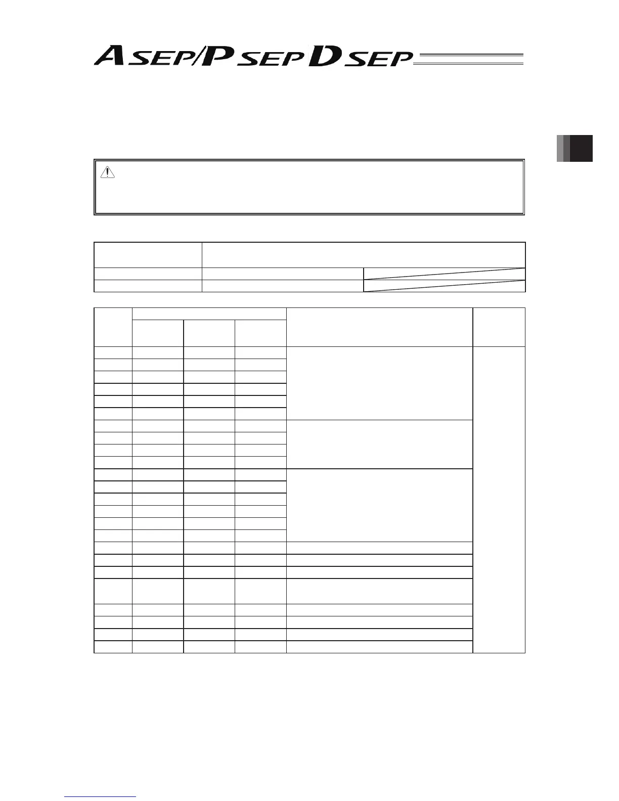
2. Wiring
2.4.3 Connection to Actuator
Connect the cables to the motor • encoder connectors.
Note:
For Simple Absolute applicable type, remove the absolute battery connector from the controller
before connecting the cable.
● Motor • Encoder Connector Specifi cations
Connector Name MOT
PG
Cable Side PADP-24V-1-S
Controller Side S24B-PADSS-1
Pin
No.
Signal Name
Contents
Applicable
Wire
Diameter
ASEP PSEP DSEP
1U
AU
Motor Driving Line
Cable
dedicated
for IAI
products
2 V VMM V
3-
B-
4 - VMM -
5W
/A W
6-
/B -
7BK
LS
-
LS* : Home Position Confi rmation Sensor
BK* : Brake Power Supply
8BK
LS
-
9LS
BK
LS
10 LS
BK
LS
11 ENA - ENA
EN* : Encoder Signal
HS* : Hall IC Signal
12 /ENA - /ENA
13 ENB ENA ENB
14 /ENB /ENA /ENB
15 ENZ ENB HS1
16 /ENZ /ENB HS2
17 5V 5V 5V Encoder Power Supply
18 /PS VPS - Encoder Line Driver Enable Output
19 GND GND GND Ground
20 LSGND LSGND HS3
LSGND : Ground for Limit Switch
HS3 : Hall IC Signal
21 NC NC NC Disconnected
22 NC NC NC Disconnected
23 NC NC NC Disconnected
24 FG FG FG Ground