41
/
2. Wiring
2.4 Wiring Method
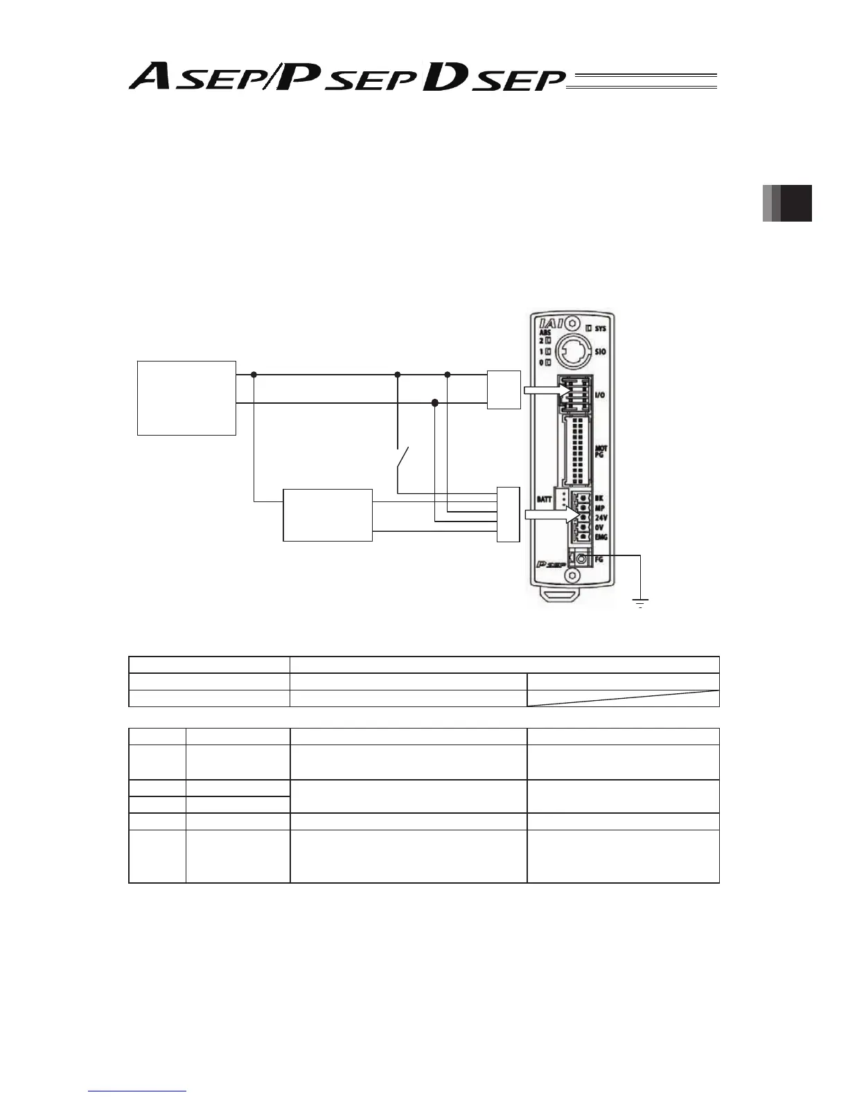
2.4.1 Wiring Layout of Power Supply Connector
The wires of the power supply and the emergency stop circuit are to be connected to the enclosed
connector (plug).
trip the sheath of the applicable wires for 7mm and insert them to the connector. Push a protrusion
beside the cable inlet with a small slotted screwdriver to open the inlet. After inserting a cable, remove
the screwdriver from the protrusion to fi x the cable.
24V DC
Power
Supply
+
24V
0V
Brake Release
Switch
(Turn ON to
Release Brake)
1 Pin
(BR)
2 Pin
(RD)
(MC1.5/5-ST-3.5)
Accessory I/O
Flat Cable
Emergency
Stop Circuit
[Refer to 2.3]
Accessory Power
Supply Connector
Class D Grounding
● Power Supply Connector
Connector Name -
Cable Side MC1.5/5-ST-3.5 Standard Accessory
Controller Side MC1.5/5-G3.5
Pin No. Signal Name Contents Applicable Wire Diameter
1 EMGIN
Input of Emergency Stop
Status Signal
(Note 1)
KIV0.5mm
2
(AWG20)
20V
Power Supply Input (24V DC ±10%) KIV1.25mm
2
(AWG16)
3 24V
4 MP Motor Driving Power Supply Line KIV1.25mm
2
(AWG16)
5BK
Brake Forced Release Power Supply
Input
(Note 2)
(24V DC ±10% 150mA)
KIV0.5mm
2
(AWG20)
(Note 1) The emergency stop status signal input determines as the system is in normal condition when 24V
DC is input and in emergency stop when 0V is input. Once in emergency stop, the actuator stops its
operation and turns the servo off.
Construct the emergency stop circuit suits for the safety category considering the entire system.
(Note 2) The brake is compulsorily released when +24V is supplied. Make the 0V in common with the 0V of the
power input. Do not apply on DSEP.