100
10. Appendix
240
19
0.02
30
26
20 66
15.5 9 15.5
13.8
57.5
50
52
50
52
26
40
10
7.5
57.5
5.1
13.3
14.5
41.5
13.3
16.5
2.7
2.8
16.5
35.5
43
52
434.5
146.5 2.5
2.1
3
11994
2.7
16
2.8
ME
SE
L
8
4.5
4.5
4.5
3
50
52
A
0
+0.012
4
5
39
24
26
813356
50 20
100
C100
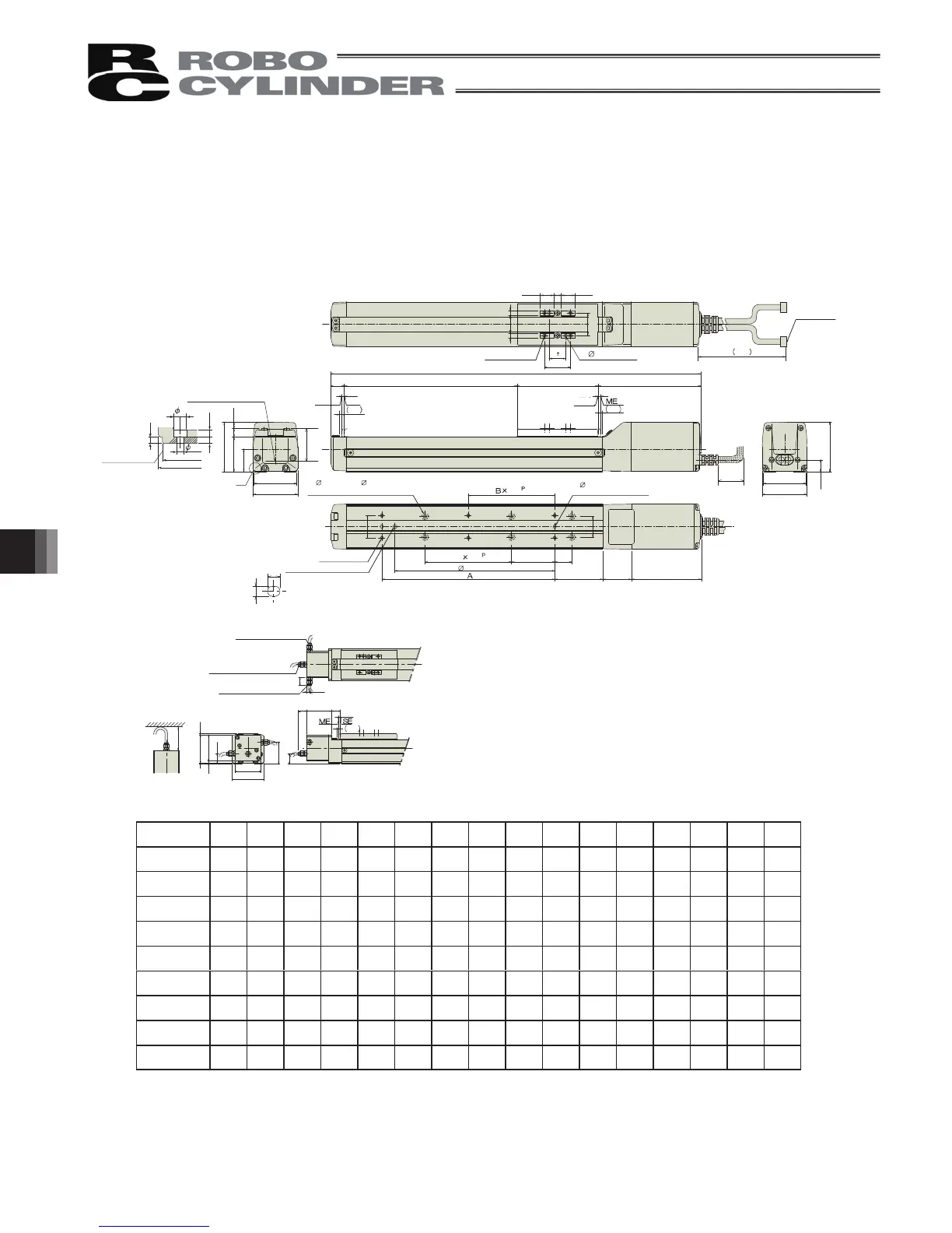
Stroke
ME : Mechanical End
SE : Stroke End
* The brake-equipped type is longer in 40mm
(53.3mm for cable end side eject type) and heavier in 0.4kg.
50 100 150 200 250 300 350 400 450 500 550 600 650 700 750 800
279 329 379 429 479 529 579 629 679 729 779 829 879 929 979 1029
A 73 100 100 200 200 300 300 400 400 500 500 600 600 700 700 800
B 0001122334455667
C 0011223344556677
D 4446688101012121414161618
E 44668810101212141416161818
H 0111111111111111
P 0 85 85 185 185 285 285 385 385 485 485 585 585 685 685 785
Weight [kg] 1.5 1.6 1.7 1.8 1.9 2.1 2.2 2.3 2.4 2.5 2.6 2.8 2.9 3.0 3.1 3.2
L
10. Appendix
10.1 External Dimensions
10.1.1 RCP2-SA5C
Reference position for
Ma moment offset
Detail view of A
(installation hole and
reference surface)
E- 4.5 through, 8, counterbore depth 4.5
(from opposite side)
D-M4, depth 7
BE: Brake cable exit
direction, end
BL: Brake cable exit
direction, left
BR: Brake cable exit
direction, right
Brake dimensions
50 or more
100 or more
Cable joint
connector
4-M4, depth 9
2-
4H7, depth 6
Home
Stroke
2- 4H7, depth 5.5 from
bottom surface of base
P (pitch of 4 hole and oblong hole)
(Tolerance between
reamed holes ±0.02)
Detail of oblong hole
Reference surface
H-oblong hole, depth 5.5 from
bottom surface of base
 Loading...


