101
10. Appendix
823 8
19.5
21
19.5
31
50
2.2
3
119115
16
2.7
3.1
L
13.8
59.5
56
58
28
43
10
6.5
59.5
56
A
58
50
240
ME
SE
14.3
41.7
13.3
18.5
3.1
2.7
18.5
3.5
37.5
6.5 43
48.5
1
43
58
13.3
5.1
8
4.5
4.5
5
5
56
58
32
0.02
B
C
0
+0.012
4
5
40
20
31
31
100
8133
19.5
A75
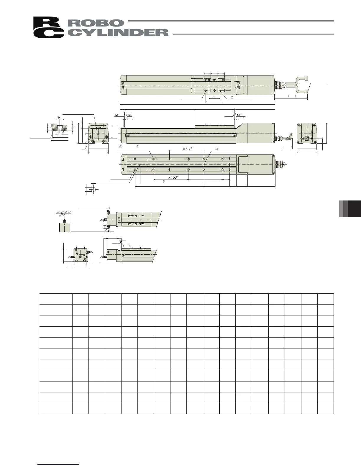
50 100 150 200 250 300 350 400 450 500 550 600 650 700 750 800
L 300 350 400 450 500 550 600 650 700 750 800 850 900 950 1000 1050
A 0 100 100 200 200 300 300 400 400 500 500 600 600 700 700 800
B 0001122334455667
C 0011223344556677
D 4 6 6 8 8 10 10 12 12 14 14 16 16 18 18 20
E 2333333333333333
F 44668810101212141416161818
H 0111111111111111
P 0 85 85 185 185 285 285 385 385 485 485 585 585 685 685 785
Weight [kg] 1.8 2.0 2.1 2.2 2.4 2.5 2.7 2.8 2.9 3.1 3.2 3.4 3.5 3.6 3.8 3.9
Stroke
10.1.2 RCP2-SA6C
Reference position for
Ma moment offset
Detail view of A
(installation hole and
reference surface)
F- 4.5 through, 8, counterbore depth 4.5
(from opposite side)
H-oblong hole, depth 5.5 from
bottom surface of base
BE: Brake cable exit
direction, end
BL: Brake cable exit
direction, left
BR: Brake cable exit
direction, right
Brake dimensions
100 or more
Cable joint
connector
4-M5, depth 9
2-
5H7, depth 6
Home
Stroke
E- 4H7 depth 5.5 from
bottom surface of base
P(pitch of 4 holeandoblonghole)
Detail of oblong hole
(Tolerance
between reamed
holes 0.02)
Reference surface
D-M5, depth 9
ME : Mechanical End
SE : Stroke End
* The brake-equipped type is longer in 40mm
(53.3mm for cable end side eject type) and heavier in 0.4kg.
 Loading...


