103
10. Appendix
57
60
55
41.5
27
60
A
55
4.51
55
60
126
60
50
32
0.02
40.6
32
23.4
19.5 19.5
21
12
25
A
L
5
113
90
55
15
25
5
16
S
126
S.E.
M.E.
M.E.
240
36.5
52
1
55
53
27
60
0
+0.012
4
5
36
18
18
C
30
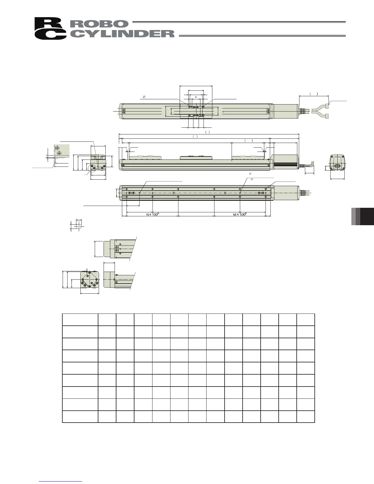
10.1.4 RCP2-SS7C
Reference position for
Ma moment offset
Detail view of A
Oblong hole, depth 6 from
bottom surface of base
Detail of oblong hole
Brake dimensions
100 or more
Cable joint
connector
4-M5, depth 10
2- 5H7, effective depth 10
Home
S (Stroke)
4- 4H7, depth 6 from bottom
surface of base
50 (pitch between reamed
hole and oblong hole)
100 (Reamed hole pitch)
(90 at 50 ST)
B (Reamed hole pitch)
100 (Reamed
hole pitch)
(Tolerance
between reamed
holes 0.02)
D-M5, depth 8
50 100 150 200 250 300 350 400 450 500 550 600
L 351 401 451 501 551 601 651 701 751 801 851 901
A 226 276 326 376 426 476 526 576 626 676 726 776
B 0 40 90 140 190 240 290 340 390 440 490 540
C 90 40 90 140 190 40 90 140 190 40 90 140
D 6 8 8 8 8 12 12 12 12 16 16 16
M 111112222333
N 011112222333
Weight [kg] 3.1 3.4 3.7 4.0 4.3 4.7 5.0 5.4 5.7 6.1 6.4 6.7
Stroke
Reference surface
(3-
4H7 at 50 ST,
depth 6 from bottom
surface of base)
55
99
ME : Mechanical End
SE : Stroke End
* The brake-equipped type is longer in 24.5mm and heavier in 0.3kg.
 Loading...


