117
10. Appendix
50
0.5
70
59
34
80
43
5
1
74
80
5
5
138
68
14
3030
A
170
L
116
14
170
90
15
45
0.02
75
15
7.5
56
45
45
35
17
70
80
55
34
77
73
24
240
A
48
F
15
15
45
0
+0.012
5
6
N
N
50 100 150 200 250 300 350 400 450 500 550 600 650 700 750 800
L 435 485 535 585 635 685 735 785 835 885 935 985 1035 1085 1135 1185
A 280 330 380 430 480 530 580 630 680 730 780 830 880 930 980 1030
B 50 100 150 200 250 300 350 400 450 500 550 600 650 700 750 800
D 8 8 8 10 12 12 12 14 16 16 16 18 20 20 20 22
F 50 100 150 0 50 100 150 0 50 100 150 0 50 100 150 0
N 1112222333344445
850 900 950 1000
L 1235 1285 1335 1385
A 1080 1130 1180 1230
B 850 900 950 1000
D24242426
F501001500
N 5556
Stroke
Stroke
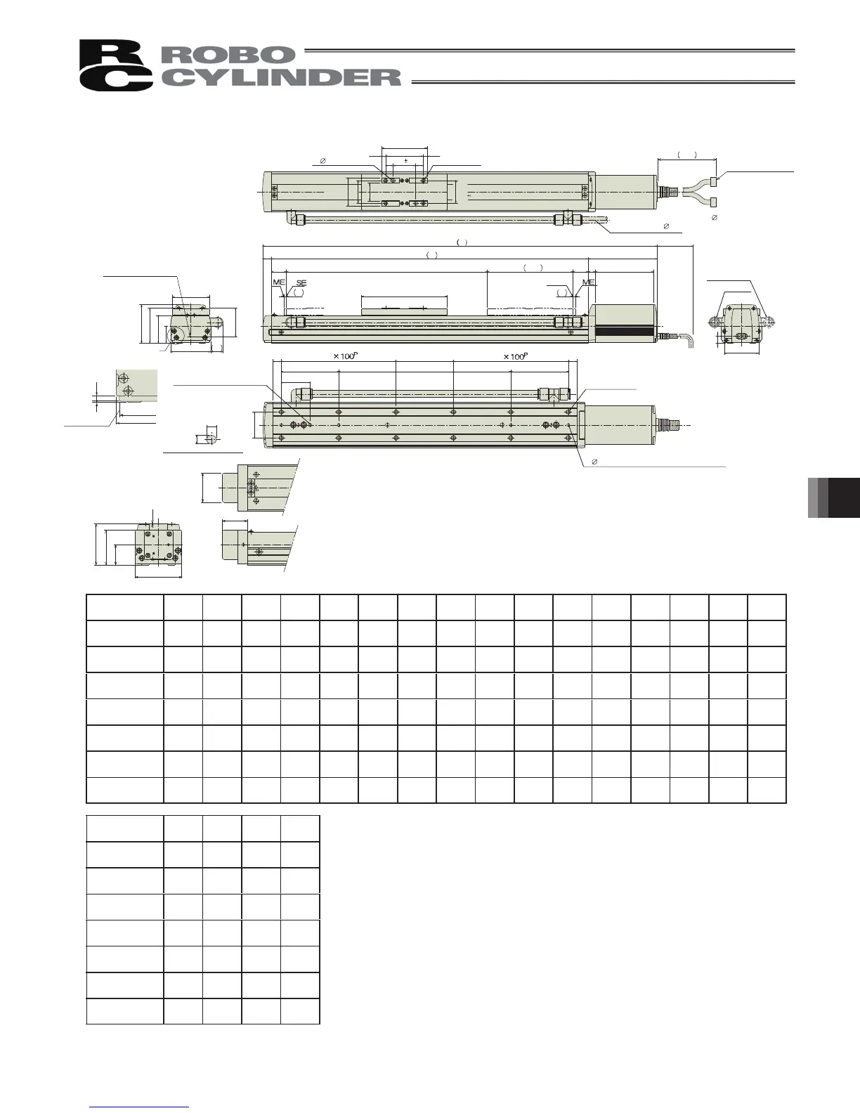
10.1.18 RCP2CR-HS8C
Brake dimensions
4-
5H7, depth 6 from bottom surface of base
Offset reference
position for Ma moment
D-M8, depth 10
Oblong hole, depth 6
from bottom surface of
Applicable tube outer diameter:
12
(inner diameter:
8)
Home
4-M8, depth 10
(Tolerance
between reamed
holes 0.02)
Detail view of oblong hole
Opposite side
(option)
2- 8H7, depth 10
100 (Reamed hole pitch)
50 (pitch between reamed hole and oblong hole)
B (Rreamed hole pitch)
100 (Reamed hole pitch)
Standard
S (stroke)
100 or more
Detail view of A
Reference surface
Cable joint connector
Weight [kg] 15.4 15.9 16.5 17.0
Weight [kg] 7.0 7.5 8.0 8.5 9.0 9.6 10.1 10.6 11.2 11.7 12.3 12.7 13.3 13.8 14.4 14.9
ME : Mechanical End
SE : Stroke End
* The brake-equipped type is longer than the standard type in 26mm.
 Loading...


