See the documentation for the system the 7226 is attaching to for information about which features are supported.
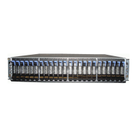
The 7226 Storage Enclosure has the following components on the front of the unit:
Bays 1 and 2
1 and 2 on the front of the 7226 Storage Enclosure (see Figure 1), can each accommodate a single storage device, a
DVD slim drive tray, or a bay blank.
Power® Switch and LED
The power switch 3 is a push-button switch that enables the power to be turned on or off. Push and release the button
to toggle power to the 7226 Storage Enclosure on and off. The green power-on LED on the power switch is illuminated
when the 7226 Storage Enclosure is powered on.
Note: If power to the 7226-1U3 is lost, the user needs to press the power switch to again provide power to the devices
in the 7226.
Fan Fault LED
The amber fan fault LED 4 indicates a fan fault when lit.
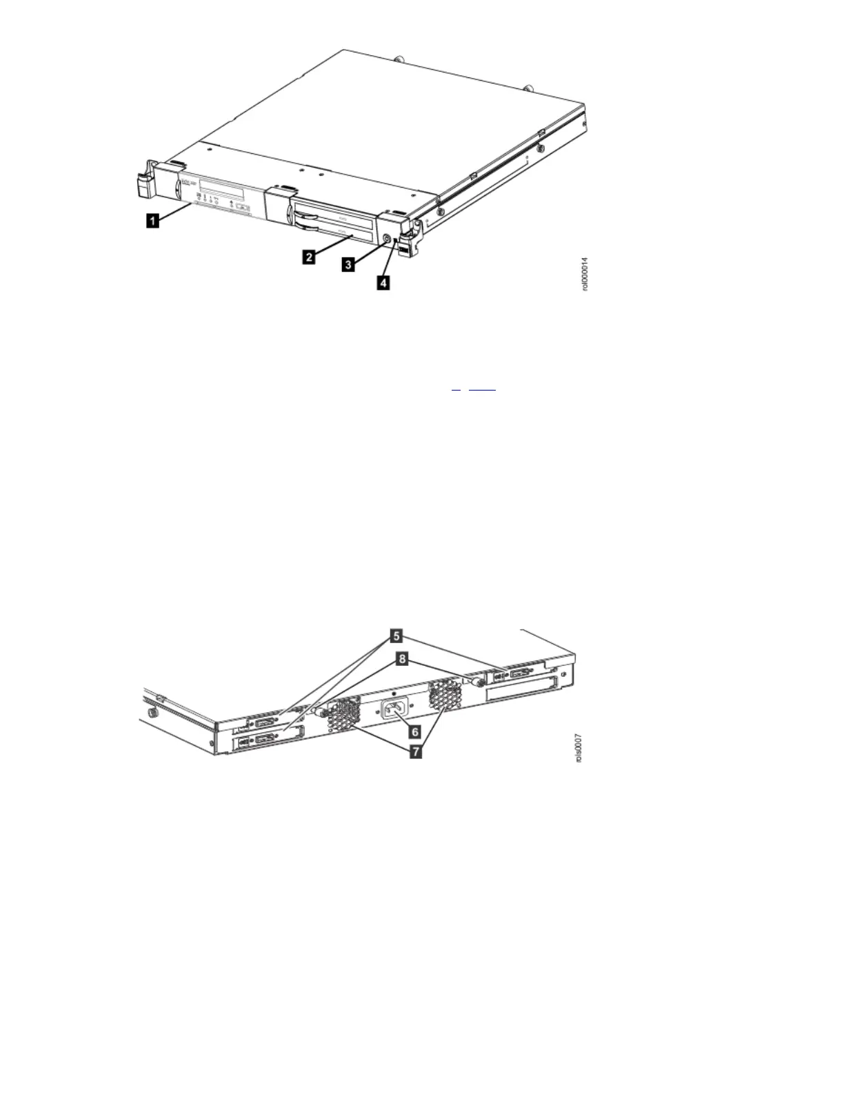
The rear of the 7226 Storage Enclosure has the following components:
Figure 2. Rear view of the 7226 Storage Enclosure
Back Plates
Back Plates 5 provide rear mounted cable connectors for the storage devices in the 7226 Storage Enclosure.
Power Cable Connector
The 7226 Storage Enclosure receives power from a power source through a cable that is connected to the power cable
connector 6.
Cooling Fans
Two internal cooling fans are used to regulate the internal temperature of the enclosure. Air exits the 7226 Storage
Enclosure at the cooling fan locations 7.
Note: To ensure proper operation, place the 7226 Storage Enclosure so that the front of the enclosure and the cooling
fan exits at the rear of the enclosure have sufficient clearance to ensure airflow.
Note: The cooling fans are a part of the enclosure assembly and cannot be replaced separately.
Thumbscrews
The Thumbscrews are used to attach or remove the top cover of the 7226 Storage Enclosure 8.

 Loading...