Repair Information 4-9
Bays 1, 2, 3 (5.25-In. Internal/External Bays)
•
Disconnect any cables on the drive (note location of cables).
NOTE:
For easiest removal of the power supply connector from the drive,
follow these instructions:
1. Place your right hand beneath the connector.
2. Grasp the sides of the connector.
3. Apply slight downward pressure as you slide the connector from side
to side and toward the back of the system unit.
The connector may be difficult to remove. It is not "locked" into the drive.
•
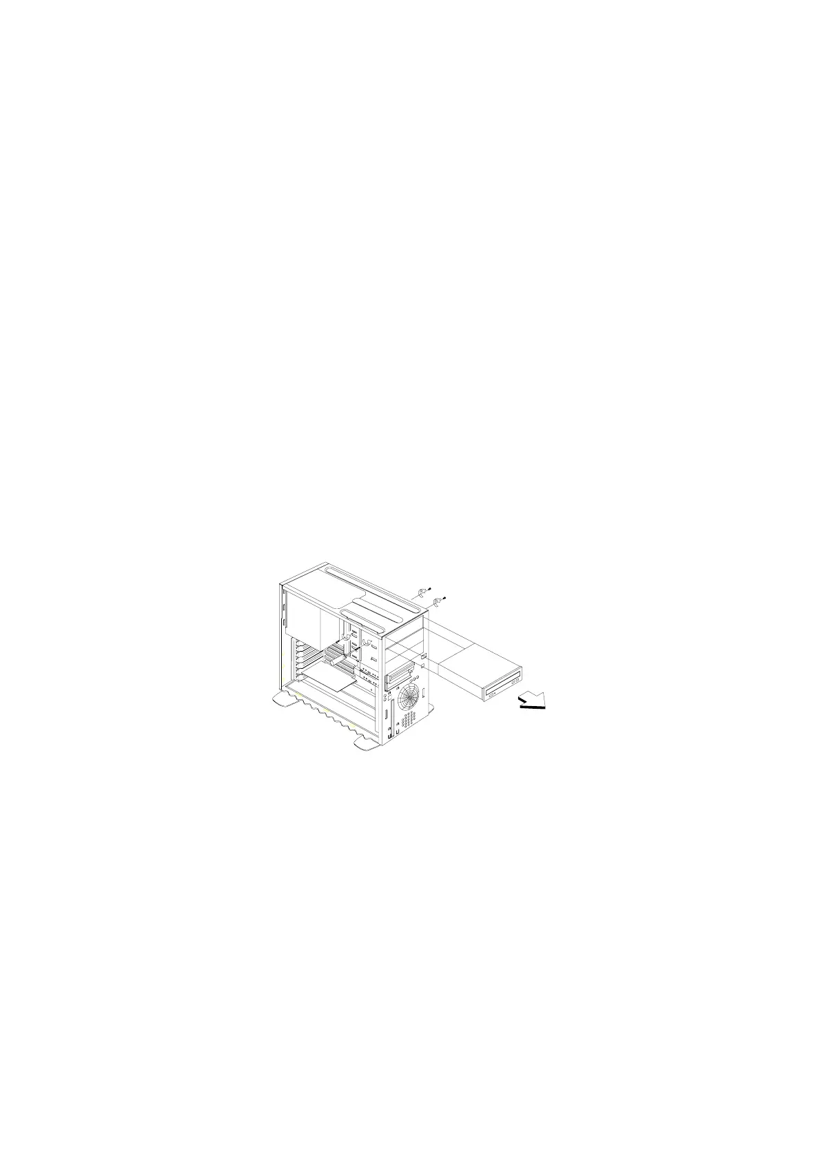
Remove the screws.
WARNING:
For 5.25-In. hard disk drive installation, it uses different
screws from 3.5-In. hard disk drive which may installed in Bay 5.
•
Pull out the drive.
Figure 4- 7 Bay 1 (5.25-In.)
 Loading...


