16. Rotate the adapter retainer clip clockwise until it covers the tab at approximately a
45 degree angle. See the following illustration.
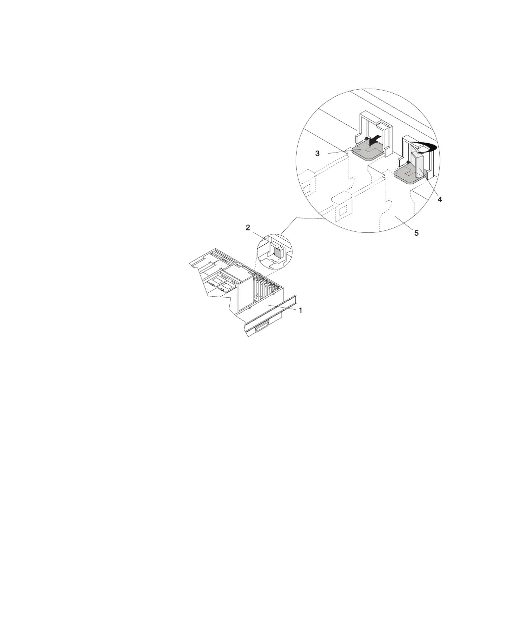
1 System Unit
2 Adapter Retainer Assembly (in the unlocked position)
3 Adapter Retainer Assembly (retainer seat down and the retainer
clip in the unlocked position)
4 Adapter Retainer Assembly (retainer seat down and the retainer
clip in the locked position)
5 PCI Adapter (dotted lines) being locked into position
17. Replace the service access cover as described in “Service Access Cover
Replacement (Model 6C4)” on page 55 or “Service Access Cover Replacement
(Model 6E4)” on page 58.
18. On a Model 6C4, push the system drawer back into the operating position as
described in “Returning the Model 6C4 to the Operating Position” on page 54.
19. Connect the adapter cables.
20. On a Model 6C4, route the cables through the cable management arm.
21. On a Model 6C4, close the rack doors.
On a Model 6E4, close the bezel door.
Chapter 4. Installing Options 91
 Loading...


