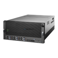
Adding or Replacing a Processor Card
Notes:
1. Adding an additional processor card or installing a new process card into your
system may require the updating of the system firmware.
2. Before handling any card, board, or memory DIMM, touch any metal surface of the
chassis with one hand to minimize static electric discharge. Refer to “Handling
Static-Sensitive Devices” on page 50.
3. If your system is configured with one processor card, it should be placed into
location U0.1-P1-C1 on the CEC backplane. The remaining processor connector
must have the processor filler panel in place. The filler panel protects the connector
located on the CEC backplane from dust or damage and assists in air flow and
cooling.
4. If a second processor is to be added to your system, remove the protective filler
panel from the system and install the new processor assembly into the secondary
processor bay location U0.1-P1-C2.
To add or replace a processor card, do the following:
1. From the bottom of the processor assembly lift the side access cover. The cover is
held to the top of the processor assembly by four hinges. Pivot the cover up to
reveal the memory DIMMs or DIMM connectors. Install the memory DIMMs as
described in “Memory DIMMs” on page 113.
2. Pivot the processor assembly cover back into the closed position.
3. Grasp the release handles located on top of the processor assembly. Pivot the
handle upward to 90 degrees. This action puts the handle cams into the correct
position to help seat the processor card connector into the docking connector
located on the CEC backplane.
Attention: To prevent damage to the processor card assembly and the processor
card connector, open or close both release handles at the same time.
4. Align the processor card connector with the docking connector located on the CEC
backplane.
5. Carefully insert the processor card assembly into the system.
6. As the processor connector is seated into its CEC backplane docking connector,
begin lowering the processor assembly release handles. This action correctly seats
and locks the processor assembly to the CEC backplane.
7. If necessary, replace the processor filler panel.
Chapter 4. Installing Options 111

 Loading...


