Step 24. Connect the Power Cables to Electrical Outlets
Connect the power source to the system unit.
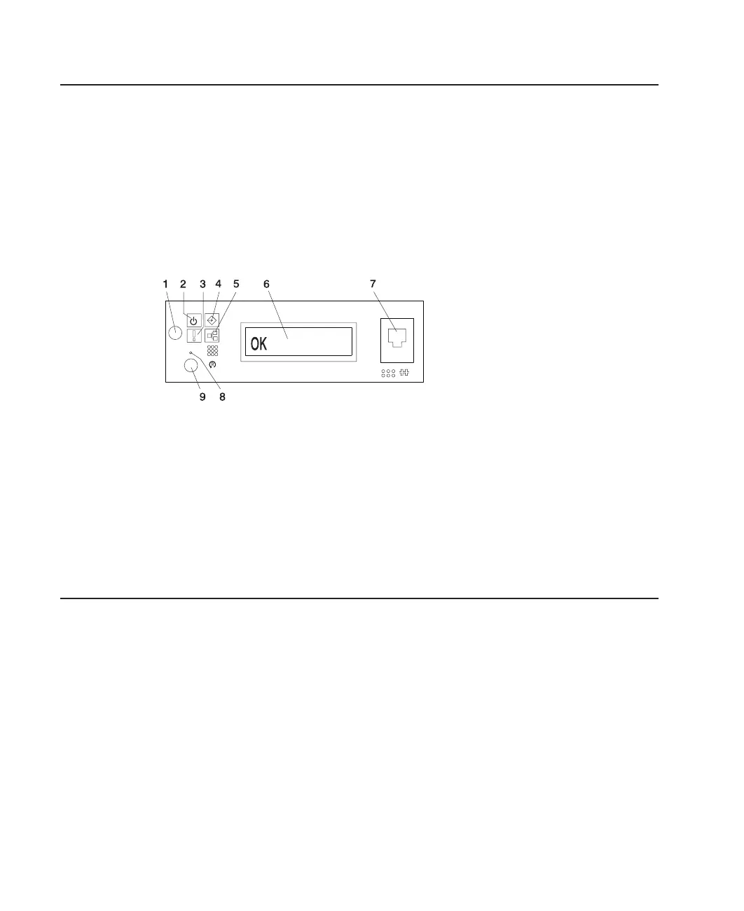
When connected to the power source, the operator panel displays OK, and the green
power LED blinks at a fast rate. 9xxx checkpoints appear in the operator panel display.
When the power-on sequence is complete, the power LER on the operator panel stops
blinking and remains on.
The following illustration shows the operator panel in standby mode with the OK
displayed in the operator panel.
1 Power-On Button 6 Operator Panel Display
2 Power LED 7 (FS1) Front Serial Connector
(RJ48 Connector)
3 Attention LED 8 CSP Reset Button (Pinhole)
4 SCSI Port Activity 9 System Reset Button
5 Ethernet Port Activity
If your system does not stop in standby mode, check all cables for good connection. If
you cannot find a problem, call your support center for assistance.
Step 25. Your System Unit Is Now Set Up
Arrange your system unit and attached devices so that you can use them comfortably.
If the AIX operating system is not preinstalled on your system and you want to install
the AIX operating system now, refer to the
AIX Installation Guide
, order number
SC23-4112. Return here to continue after your operating system is installed.
40 Eserver
pSeries 630 Model 6C4 and Model 6E4 Installation Guide
 Loading...


