6. Lift the handle until it is perpendicular (90 degrees) to the top of the power supply.
By placing the handle perpendicular to the top of the power supply, the base or
hinged portion of each handle acts as a cam and will gently pry the power supply
from its connector located on the CEC backplane.
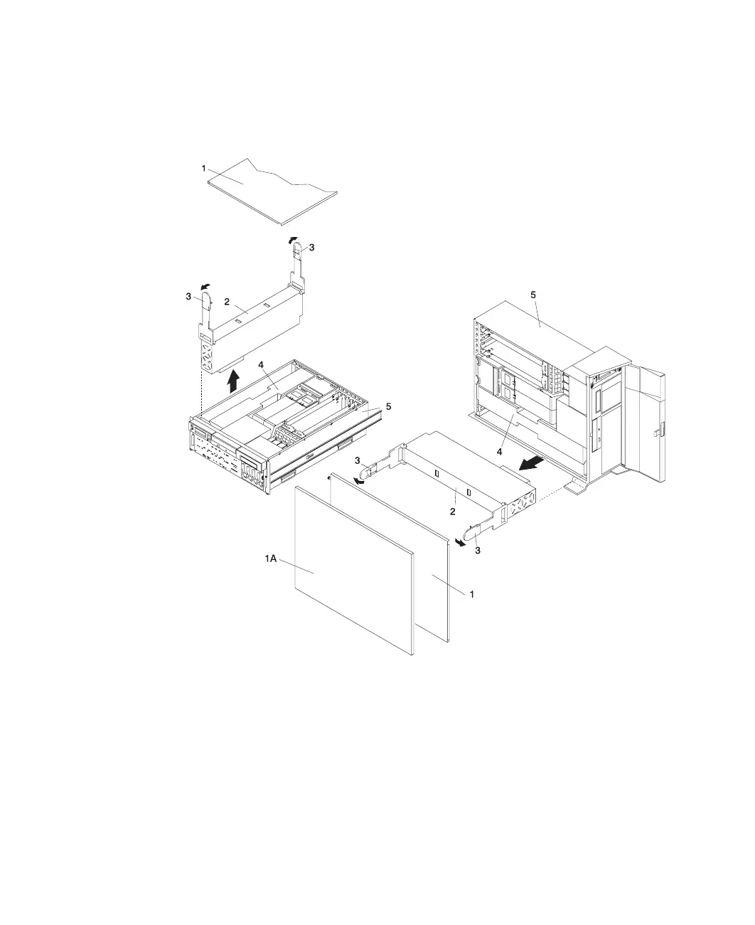
1A Outer Side Cover (Model 6E4
only)
3 Power Supply Release Handle
1 Service Access Cover 4 Power Supply Filler Panel
2 Primary Power Supply 5 System Unit
7. After the power supply is released from its connector, pull the power supply out of
the system.
Note: During normal operation, each power-supply bay must have either a power
supply or filler panel installed for proper cooling.
126 Eserver
pSeries 630 Model 6C4 and Model 6E4 Installation Guide
 Loading...


