J
'-
!/
-'-
/
..........
"-
I \
I 1
\ J
\.
/
A
B
Play Removed
In
The
Negative
Direction
Play Removed
In
The Positive Direction
FIGURE
67.
Tilt Detent Entry
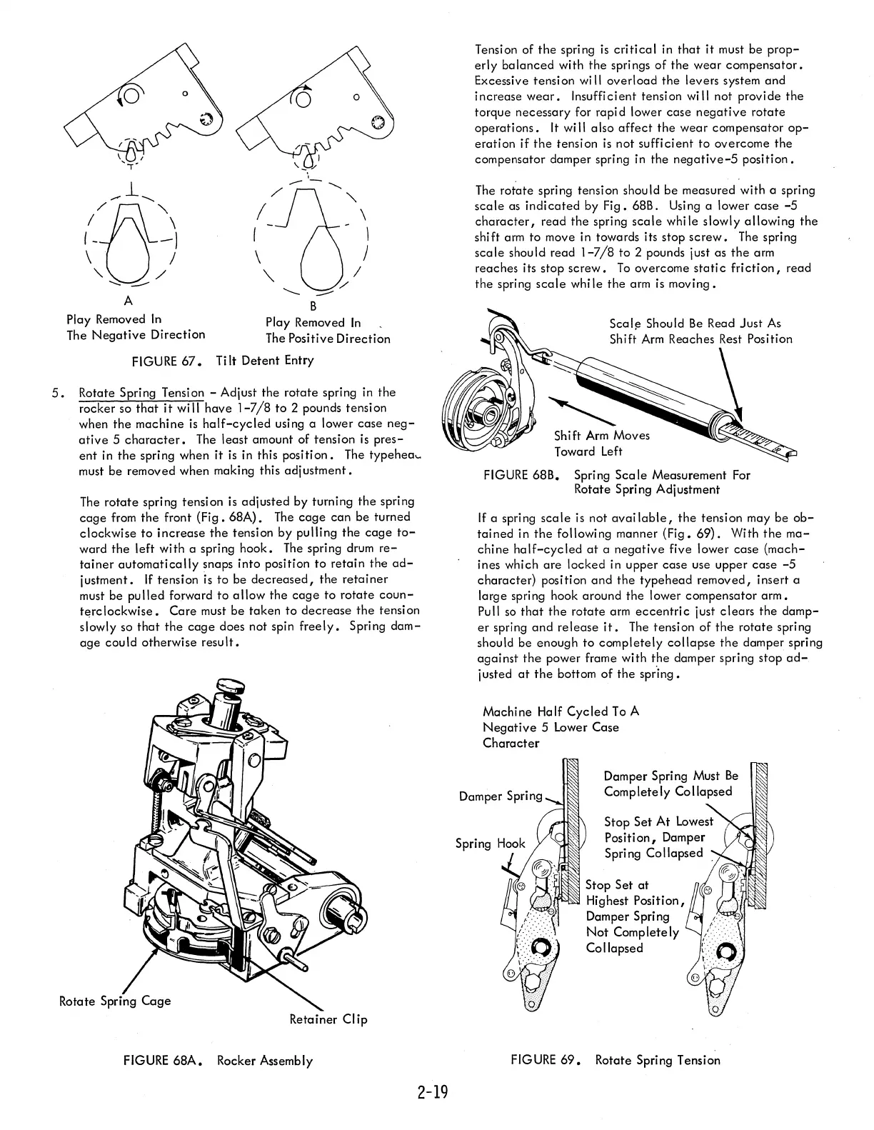
5.
Rotate Spring Tension - Adjust
the
rotate
spring
in
the
rocker so
that
it
wi
II
have
1-7/8
to
2 pounds tension
when
the
machine
is
half-cycled
using a lower case
neg-
ative
5
character.
The least amount of tension
is
pres-
ent
in
the
spring when it
is
in this positi
on.
The typehea
...
must be removed when making this
adjustment.
The
rotate
spring tension is adjusted by turning
the
spring
cage
from
the
front
(Fig.
68A).
The
cage
can be turned
clockwise to
increase
the
tension by pulling
the
cage
to-
ward
the
left with a spring hook.
The
spring drum
re-
tainer
automatically
snaps into position
to
retain
the
ad-
justment.
If
tension
is
to
be
decreased,
the
retainer
must be
pulled
forward
to
allow
the
cage
to
rotate
coun-
tE!rclockwise.
Care
must be taken to decrease
the
tension
slowly so
that
the
cage
does not spin
freely.
Spring
dam-
age
could otherwise
result.
Rotate Spr
Retainer Clip
FIGURE
68A.
Rocker Assembly
2-19
Tension of
the
spring
is
critical
in
that
it
must be
prop-
erly
balanced
with
the
springs
of
the
wear compensator.
Excessive tension
wi
II
overload
the
levers system and
increase
wear.
Insuffi ci ent tensi
on
wi
II
not provide
the
torque necessary for rapi d lower case
negative
rotate
operations.
It
will also
affect
the
wear
compensator
op-
eration
if
the
tension
is
not sufficient to overcome the
compensator damper spring in the
negative-5
position.
The
rotate spring tension should be measured with a spring
scale
as
indicated
by Fig. 68B. Using a lower case
-5
character,
read
the
spring
scale
while slowly allowing
the
shift arm to move in towards its stop
screw.
The
spring
scale
shou
Id
read
1-7/8
to 2 pounds just as
the
arm
reaches its stop
screw.
To
overcome
static
friction,
read
the
spring
scale
while
the
arm
is
moving.
Shift
Arm
Moves
Toward Left
FIGURE
68B. Spring
Scale
Measurement For
Rotate Spring Adjustment
If
a spring
scale
is
not
available,
the
tension may be
ob-
tained
in
the
following manner
(Fig.
69).
With
the
ma-
chine
half-cycled
at
a
negative
five lower case {mach-
ines which
are
locked in upper case use upper case
-5
character} position
and
the
typehead
removed, insert a
large spring hook around
the
lower compensator
arm.
Pull
so
that
the
rotate
arm
eccentric
just
clears
the
damp-
er
spring
and
release
it.
The tensi
on
of
the
rotate
spring
should be enough to completely
collapse
the
damper spring
against
the
power frame with
the
damper spring stop
ad-
justed
at
the
bottom
of
the
spr"ing.
Machine Half
Cycled
To
A
Negative
5
lower
Case
Character
Damper Spring Must
Be
Completely Collapsed
Stop
Set
at
Highest Position I
Damper Spring
Not
Completely
Collapsed
FIGURE
69.
Rotate Spring Tension
 Loading...


