With the damper spri
ng
stop a
II
the way
up,
the
damper
spring should not be
completely
collapsed.
Check
and
adjust
the
rotate
spring
to
satisfy both
conditions.
NOTE: Lower damper spring stop to bottom before
pro-
ceeding
with
sequence.
CAUTION:
The
damper spring method
is
only usable
when
it
is
impossible
to
obtain
a spring
scale.
NOTE: The
accuracy
given
to
the
next
seven coarse
alignment
adjustments determines the "band
width"
(de-
tenting
variation)
of
the
rotate
system. Each one
of
these seven adjustments contributes
to
the
band width in
a
different
manner.
Generally,
it takes
experience
in
making
each
adjustment
to
learn how much
accuracy
is
needed
to
end
up with
an
accumulated
band width which
is
acceptable.
The band width
of
the
rotate
system
should
never
exceed
.020"
nor should
any
extra time
be
spent
in trying
to
obtain one
any
less than
.0lD".
References wi
II
be
made
to
2 different methods of
ob-
taining
a
zero
rotate
character.
These methods
can
be
defined
as:
Latched
Home
-
zero
rotate
with
NO
plus or minus
rotation.
I/O
Home
-
zero
rotate with
BOTH
plus
5
and
minus 5
rotation.
6.
Rotate
Selector
Latches
a.
Form
tlie stop lugs
above
the
pOsitive
rotate
selector
latches
(Fig.
70) so
that
the
latches will reset
si-
mutaneousy
(under
the
latch
bail) just as
the
cycle
clutch
check
pawl drops
into
the ·notch on
the
check
ratchet
at
the
rest
position.
NOTE: The adjustment theory under
"tilt
selector
latches"
also
pertains to
the
rotate
selector
latches.
Form
These
Lugs
I
,
'"
\~-
-------/""\'
-
----~_i....b
FIGURE
70.
Rotate
Selector
Latches
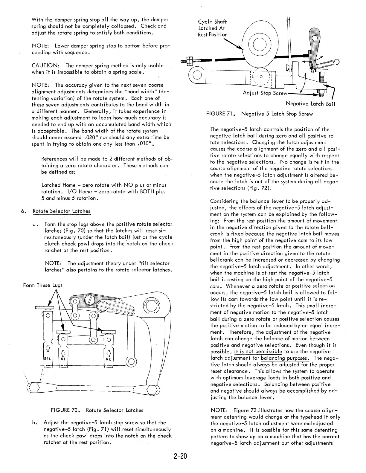
b.
Adjust
the
negative-5
latch
stop screw so
that
the
negative-5
latch
(Fig. 71) will reset simultaneously
as the
check
pawl drops
into
the notch
on
the
check
ratchet
at
the
rest positi
on.
2-20
Cycle
Shaft
Latched At
Negative
Latch
Bai
I
FIGURE
71.
Negative
5
latch
Stop Screw
The
negative-5
latch
controls the position
of
the
negative
latch
bai I during
zero
and
all
positive
ro-
tate
selections.
Changing
the
latch adjustment
causes
the
coarse
alignment
of the
zero
and
all
posi-
tive
rotate
selections
to
change
equally
with respect
to
the
negative
selections.
No
change
is
felt
in
the
coarse
alignment
of
the
negative
rotate
selections
when the
negative-5
latch
adjustment
is
altered
be-
cause
the
latch
is
out
of
the
system during
all
nega-
tive
selections
(Fig.
72).
Considering
the
balance
lever
to
be
properly
ad-
justed,
the
effects
of
the
negative-5
latch
adjust-
ment on
the
system
can
be
explained
by the
follow-
ing:
From
the
rest position
the
amount of movement
in
the
negative
direction
given
to
the
rotate
bell-
crank
is
fixed
because
the
negative
latch bai I moves
from
the
high point
of
the
negative
cam
to
its low
point.
From
the
rest position
the
amount of
move-
ment
in
the
positive
direction
given
to
the
rotate
bellcrank
can
be increased or
decreased
by changing
the
negative-5
latch
adjustment.
In
other words,
when
the
machine
is
at
rest
the
negative-5
latch
bai I
is
resting
on
the
high point
of
the
negative-5
cam. V/henev6i
Ci
zero rotate
or
positive
5e
lecti
on
occurs,
the
negative-5
latch bail
is
allowed
to
fol-
low its cam towards
the
low point until
it
is
re-
stri
cted
by the
negative-5
latch.
This
small
incre-
ment of
negative
motion
to
the
negative-5
latch
bai I during a
zero
rotate
or positive
selection
causes
the
positive motion
to
be
reduced by an equal
incre-
ment.
Therefore,
the
adjustment of the
negative
latch
can
change
the
balance
of motion
between
positive and
negative
selections.
Even though
it
is
possible,
it
is
not permissible
to
use
the
negative
latch
adjustment for
balancing
purposes.
The
nega-
tive
latch
should
always
be adjusted for
the
proper
reset
clearance.
This
allows the system
to
operate
with optimum
leverage
loads in both positive
and
negative
selections.
Balancing between positive
and
negative
should always be accomplished by
ad-
justing the ba
lance
lever.
NOTE: Figure 72 j((ustrates how the coarse
align-
ment
detenting
would
change
at
the type head
if
only
the
negative-5
latch
adjustment were maladjusted
on a
machine.
It
is
possible for this same
detenting
p"attern
to
show up on a machine
that
has
the
correct
negarive-5
latch
adjustment but
other
adjustments
 Loading...


