+5
+4
+3
+2
+1
-1
-2 -3
-4 -5
FIGURE
72.
Excessive
Negative
5
latch
Clearance
maladjusted.
For
this reasOn
it
is
best to adjust the
negative latch as specified
in
the adjustment rather
than by adjusting
it
whi
Ie
observing the effects
that
the
adjustment change will produ ce
at
the type head •
7.
Rotate
Arm
Vertical
-With
the type head removed
andthe
machine hal f-cycled
to
an upper case zero rotate
char-
acter
latched home, adjust the rotate link
so
that the
point
at
the
top
of
the rotate
arm
is
15/32"
from
the
ma-
chine sideframe.
The
compensator roller should be
1/16"
from
the top
of
the slot when this adjustment is made.
The
adjustment can be measured using the
#1
scribe line
on the Hooverometer handle as illustrated
in
Figure
73.
The
scribe line measurement makes allowance for the
thi ckness of the compensator damper spring.
The
adjustment sets up a
vertical
condition for three
points in the rotate
arm,
the
center
of the
pu
Iley,
the
rotate
arm pivot point, and the rotate link
connection.
With the rotate
arm
vertical
at
a
half-cycled
zero rotate
position, the leverage within the rotate
arm
will be the
same for positive and negative movements of the. arm.
NOTE:
The
eccentric
stud
at
the top of the rotate arm
should be turned
all
the way to the left
at
this point
to
prevent interference with subsequent adjustments.
FIGURE
73.
Rotate
link
Adjustment Measurement
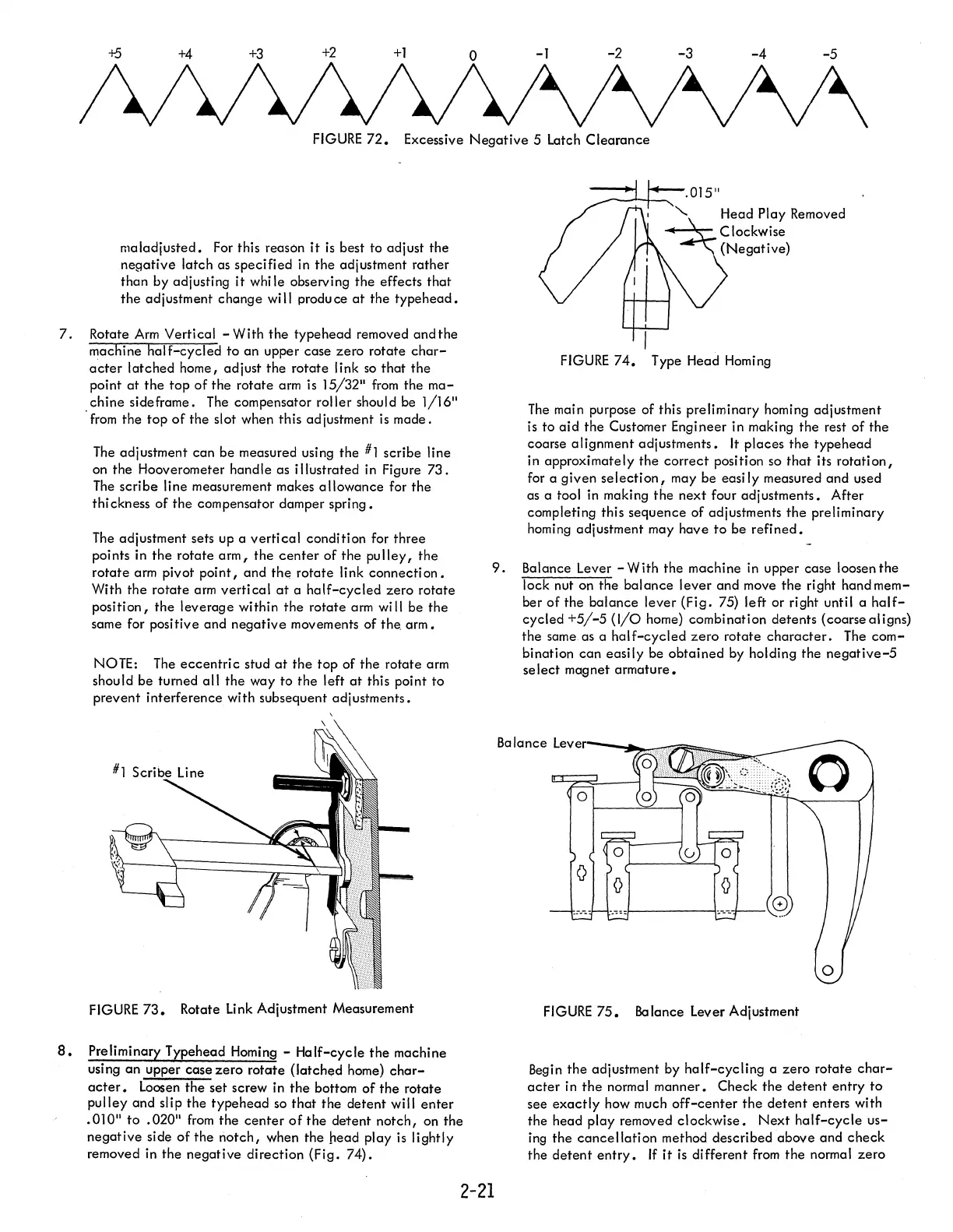
8.
Preliminary Typehead Homing - Half-cycle
the
machine
using an upper case zero rotate (latched home)
char-
acter.
Loosen the set screw
in
the
bottom
of
the rotate
pulley and slip
the
typehead
so
that
the detent will
enter
.010"
to
.020"
from
the
center
of
the detent notch, on the
negative side
of
the
notch,
when the head play
is
lightly
removed
in
the negative direction (Fig. 74).
.015"
'-
Head Play Removed
--..--
Clockwise
(Negative)
FIGURE
74.
Type Head Homing
The
main purpose of this preliminary homing adjustment
is
to
aid
the Customer Engineer in making the rest of the
coarse alignment adjustments.
It
places the typehead
in approximately the
correct
position
so
that
its
rotation,
for a given
selection,
may be easi
Iy
measured and used
as a tool
in
making the next four adjustments. After
completing this sequence of adjustments the preliminary
homing adjustment may have
to
be
refined.
9.
Balance Lever - With the machine
in
upper case loosen the
lock nut on the
balance
lever and move the right hand mem-
ber
of
the balance lever (Fig. 75) left or right until a
half-
cycled
+5/-5
(I/O
home) combination detents (coarse aligns)
the same as a
half-cycled
zero
rotate
character.
The
com-
bination
can
easily be obtained
by
holding the
negative-5
se lect magnet armature.
Ba
lance Leve
~-"""""",71ii
FIGURE
75.
Balance
lever
Adjustment
Begin
the adjustment by
half-cycling
a zero rotate
char-
acter
in
the
norma I manner. Check the
detent
entry
to
see
exactly
how much
off-center
the
detent
enters with
the head play removed clockwise.
Next
half-cycle
us-
ing
the
cancellation
method described above and
check
the
detent
entry.
If
it
is
different
from
the normal zero
2-21