rotate
character,
it
indicates
thot the
typehead
has
moved because of an
unbalanced condition between
the
positive and
negative
motions.
With
the
machine in the
half-cycled
position using
the
cancellation
method,
adjust
the
right hand member
of
the
balance
lever
left or right unti I
the
detenting
is
ex-
actly
as
it
is
when a
zero
rotate
character
is
half-cycled
normally. Changing
the
balance
lever adjustment will
not
appreciably
affect
the
detenting of
the
half-cycled
zero
rotate
character
(latched
home).
NOTE: The nut on
the
balance
lever screw can be left
loose
unti I
the
correct
adjustment
is
obtained.
Be
sure
not
to
move
the
adjustment when tightening
the
nut.
In
(Figure 76)
the
effects
of
the
wear compensator
are
dis-.
regarded
and
all
adjustments
are
correct
except
the
bal-
ance
lever.
The
right hand member of
the
balance
lever
is
maladjusted too far to
the
left creating too much
nega-
tive
motion and not enough positive motion. Looking
at
the positive side
of
Figure
76
you
can
see
that
the
mal-
adjusted
balance
lever causes a progressive
loss
of
motion
to
the
rotate
bellcrank
from
the
zero
to
a positive five
rotate
position.
The
greatest
loss
of
motion
is
felt
at
the
positive five position because
the
left
end
of
the
balance
lever
receives
the
most motion for this
selection.
When
the
negative
side of
the
balance
lever
is
operated,
the
ma
ladjusted ba lance
lever
causes
the
rotate
bellcrank
to
receive
an
excessive amount
of
motion as
illustrated
by
the
detenting
of
the
negative
five rotate position.
This
excessive motion
is
felt
equally
in
all
of
the
negative
selections
because
the
negative
end of
the
balance
lever
receives
the
same motion
from
the
cam for
all
negative
selections.
The
progressive
loss
of motion
felt
from
the
negative
five to
the
negative
one rotate position is caused
by
the
positive side
of
the
balance
lever.
It
produces a
deficiency
of
motion in
the
negative
selections just as
it
did during
the
positive
selections.
Notice
the
detenting
of a
negative
one
selection
in
Fig-
ure
76.
This
selection
combines
thp.
error
of
a positive
four and a
negative
five causing
the
negative
one
to
be
the
worst
detenting
selection
with respect to
the
zero
rotate
selection.
Although
the
cancellation
method
(+5/-5)
combines even a
greater
error than
the
negative
one
selection,
either
one may be used to
effectively
make
the
balance
lever adjustment. Checking
the
de-
tenting
of
the
other
positions
is
not
necessary.
+5
+4
+3
+2
+1
/'
/\
I \ I r
I A I
...
~
/
/
'-.:!:J../
V
/\
.1\
/2~
I
,
I'
}.
/
1\
I
L~
I
\
L"",\
I \
I
\
V
"
0
If
the
balance
lever were out
af
adjustment in
the
oppo-
site
direction so
that
there was too much positive and not
enough
negative
motion,
the
error
pattern
would remain
the
same
except
that
the
detents would move towards
the
opposite side
of
the
detent
notches.
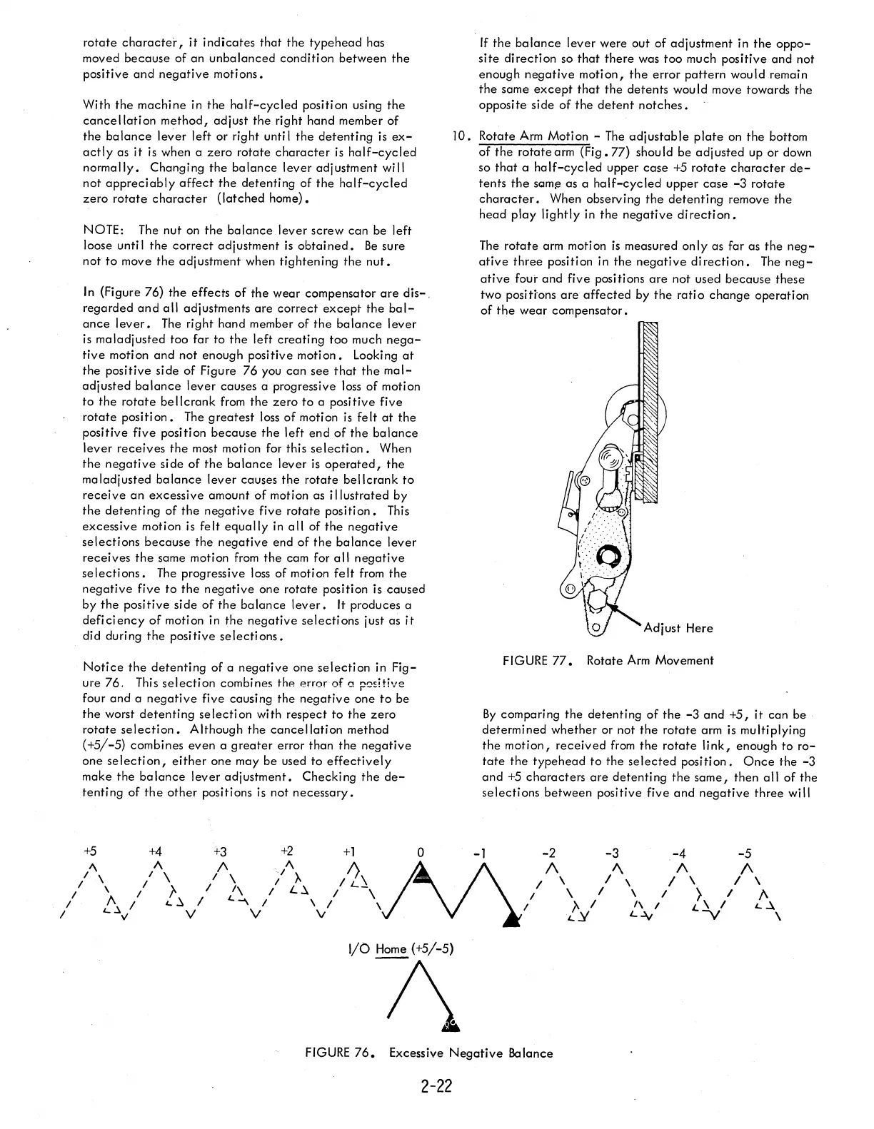
JO.
Rotate
Arm
Motion -
The
adjustable
plate
on
the
bottom
of
the
rotate
arm (Fig. 77) shou
Id
be adj usted up or down
so
that
a
half-cycled
upper case
+5
rotate
character
de-
tents
the
SQm~
as a
half-cycled
upper
case
-3
rotate
character.
When observing
the
detenting
remove
the
head play lightly in
the
negative
direction.
The
rotate
arm motion
is
measured only as far as
the
neg-
ative
three position in
the
negative
direction.
The
neg-
ative
foui' and five positions
are
not used because these
two
positi'ons
are
affected
by
the
ratio
change
operation
of
the
wear compensator.
FIGURE
77.
Rotate
Arm
Movement
By
comparing the detenting
of
the
-3
and
+5,
it can be .
determined whether or not
the
rotate arm
is
multiplying
the
motion,
received
from
the
rotate
link,
enough to
ro-
tate
the
typehead
to
the
selected
position.
Once
the
-3
and
+5
characters
are
detenting
the
same,
then
all
of
the
selections
between positive five
and
negative
three will
-1 -2 -3
.-4
-5
1\
/,
I
\
/
I
\
I
[y
/
/\
f\.
\ / \ / \
\ / } / A
1\
I L \ / L. ~
L~
-y
\
VOH7\
FIGURE
76.
Excessive
Negative
Balance
2-22