This
adjustment insures
that
the
backspace pawl will not
be prevented
from
bottoming in its rack during a
back-
space
operation.
The
tab
lever rest position also
direct-
ly affects
the
adjustments
of
the
tab mechanism.
It
de-
termines how much motion must be provided
to
the
tab
lever
to
properly remove
the
backspace
and
escapement
pawls
from
their
racks during a tab
operation.
3.
Backspace Rack - With the backspace rack in
the
rest
position, a
clearance
of
.005"
to
.015"
should exist
be-
tween the working surfaces
of
the
rack tooth and the .
backspace pawl
(Fig.
138). Adjust
the
hexagon headed
screw
in
the backspace
bellcrank
to obtain this
condition.
Backspace Bellcrank.
__
c-----,
Adjusting
Stud-----
Backspace Rack
FIGURE
138.
Backspace Rack Adjustment
The
adjustment minimizes
lod
motion
in
the
mechanism
and insures
that
the
backspace pawl
wi
II
positively reset
into the next rock tooth
at
the
completion of a
back-
space
operation.
Excessive
clearance
can contribute
to
escapement problems as well as backspace failures by
allowing
the
backspace pawl
to
hold
the
carrier against
a backspace
racK
tooth.
Partial spacing
wi
II
result
if
the
carrier
alternates
holding on the escapement pawl
and
the
backspace
pawl.
.
4.
Intermediate Lever - With
the
backspace cam manually
operated
to the high
point,
the
escapement pawl should
just fail to drop
int.o
the
preceding rack tooth causing
the
manual backspace operation to
fail.
Adjust
the
in-
termediate
lever
pivot screw forward
or
back in its
elon-
gated mounting hole
to
obtain
this condition
(Fig.
139).
The
adjustment may
be
gauged
by feeling the motion
of
the
rack as
it
is
manually moved
from
its rest position
into
contact
with
the
backspace
pawl.
The
movement
should be equal
to
the
adjustment
clearance.
The
check
should be made
at
both extreme positions
of
the
carrier
so as
to
include
the
difference in mainspring tension in
the
check
• Check
the
resetting of
the
pawl
at
both
po-
sitions by operating the backspace bellcrank manually
and
releasing
it
slowly.
The
rear portion
of
the
intermediate lever is supplied
with the same amount
of
motion
from
the
hexagaon
head-
ed
screw
on
the
bellcrank
regardless
of
any
change in
the
front
to
rear position
of
the
intermediate
lever.
Therefore,
the
difference in throw to
the
backspace rack
is
achieved,
when changing
the
front
to
rear position of
the
intermediate
lever,
by increasing or decreasing
the
2-42
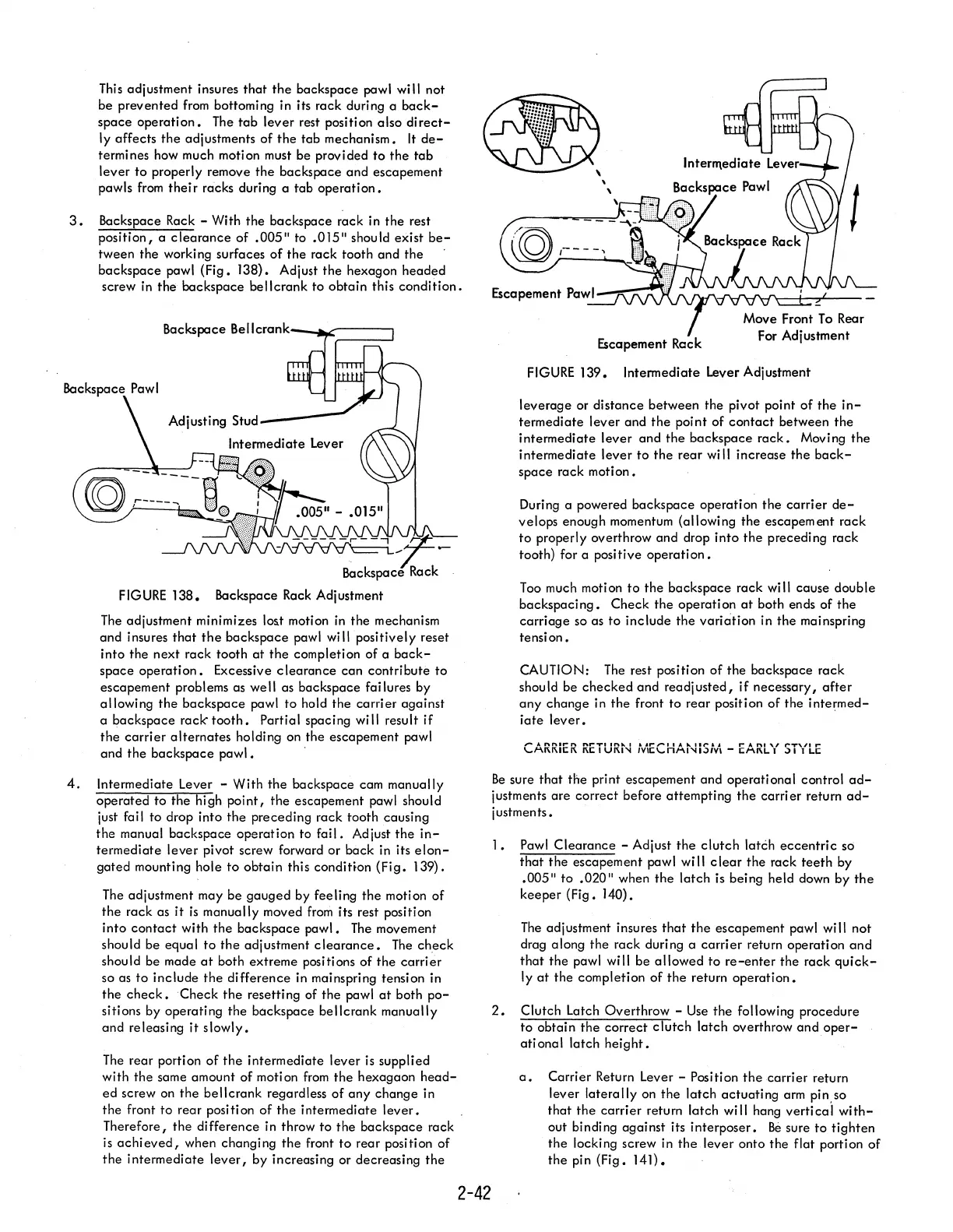
Escapement Reck
FIGURE
139.
Intermediate Lever Adjustment
leverage or distance between the pivot point
of
the
in-
termediate lever and
the
point of
contact
between
the
intermediate lever
and
the
backspace
rack.
Moving
the
intermediate lever
to
the
rear will increase
the
back-
space
rack motion.
During a powered backspace operation
the
carrier
de-
velops enough momentum (allowing
the
escapement rack
to
properly overthrow and drop into
the
preceding rack
tooth) for a positive
operation.
Too
much motion
to
the
backspace rack
wi
II
cause double
backspacing.
Check
the
operation
at
both ends of
the
carriage
so as
to
include
the
variation
in
the
mainspring
tension.
CAUTION:
The
rest position
of
the
backspace rack
should be
checked
and
readjusted,
if
necessary,
after
any
change in
the
front
to
rear position
of
the
intermed-
iate
lever.
,..."
nnll-n
"'
.........
1."
....
I
....
,..,....,
A
10.11'-&..
,..
A
ftl
"
r""T"'"
r
\..,1-\1\1\11;1\ 1\1; 1
UI\I
....
/V\I;\..,nl-\l
....
I.)/V\
-
I;I-\I\L
I
.)
1 1
LI;
Be
sure
that
the
print escapement and operational control
ad-
justments
are
correct before attempting
the
carrier
return
ad-
justments.
1.
Pawl
Clearance
- Adjust
the
clutch
latCh
eccentric
sCi
that
the
escapement pawl will
clear
the
rack
teeth
by
.005"
to
.020"
when
the
latch
is being held down by
the
keeper
(Fig. 140).
The
adjustment insures
that
the
escapement pawl
wi
II
not
drag along the rack during a
carrier
return operation
and
that
the
pawl
wi
II
be a
II
owed
to
re-enter
the
rack qui
ck-
Iy
at
the
completion
of
the
return
operation.
2.
Clutch Latch Overthrow -
Use
the
following procedure
to
obtain
the
correct
clutch
latch overthrow
and
oper-
ati ona I latch
height.
a.
Carrier Return Lever - Position
the
carrier return
lever
laterally
on
the
latch
actuating
arm pin,so
that
the
carrier
return latch will hang
vertical
with-
out binding against its interposer.
Be
sure
to
tighten
the
locking screw in
the
lever onto the flat portion
of
the
pin (Fig.
14l).