.005"
to
.020"
Clutch Latch
Eccentri c
---~'-J
FIGURE
140
• . Pawl
Clearance
Adjustment
b.
Carrier Return Latch
Arm
Adjusting Screw (over-
throw) - With
the
carrier
return cam on
the
high
point adjust the latch arm adjusting screw (Fig.
14
I)
so
that
the clutch-Iotch will overthrow
the
lotching
surface of
the
keeper by
.030"
to
.040".
Be
sure
that
the
platen and feed rolls
are
installed
and
the
index
selector
lever is in
the
double index position
when checking this adjustr;'ent.
Adj usti
ng
Screw
Carrier
Return
"'"---Latch
Arm
FIGURE
141.
Clutch Latch Overthrow
Adjustment
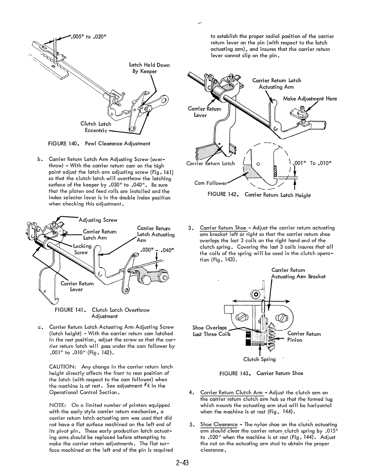
c.
Carrier Return Latch Actuating
Arm
Adjusting Screw
(latch height) - With the
carrier
return cam latched
in
the
rest position, adjust the screw so
that
the
car-
rier return latch will pass under the cam follower by
.001"
to
.0lO"
(Fig. 142).
CAUTION: Any change in
the
carrier
return latch
height
directly
affects
the
front to rear position
of
the
lotch (with respect to
the
cam follower) when
the
machine is
at
rest.
See
adjustment #4 in the
Operational
Control
Section.
NOTE:
On
a limited number of printers equipped
with
the
early
style
carrier
return mechanism, a
carrier
return latch
actuating
arm was used
that
did
not have a flat surface machined
on
the
left end
of
its pivot
pin.
These
early
production latch
actuat-
ing arms should be
replaced
before attempting
to
make
the
carrier
return adjustments.
The
flat
sur-
face
machined on
the
left end
of
the
pin
is
required
to establish
the
proper radial position
of
the
carrier
return
lever
on
the
pin (with respect
to
the
latch
actuating
arm), and insures
that
the
carrier
return
lever cannot slip on
the
pin.
001"
To
.010"
Cam
Fol
FIGURE
142.
Carrier Return Latch Height
3.
Carrier Return Shoe - Adjust
the
carrier
return
actuating
arm
bracket
left
or
right so
that
the
carrier
return shoe
overlaps
the
last 3 coi
Is
on
the
right hand end
of
the
clutch spring. Covering
the
last 3 coils insures
that
all
the
coils
of
the
spring will
be
used in
the
clutch
opera-
tion (Fig. 143).
2-43
Carrier
Return
Actuating
Arm
Bracket
Shoe Overlaps
-~:..:::::u:rrMllirl':
Last
Three Coi
Is
Clutch Spring
FIGURE
143.
Carrier
Return Shoe
4.
Carrier Return Clutch
Arm
- Adjust the
clutch
arm
on
the
carrier
return
clutch
arm hub so
that
the formed lug
whi ch mounts the ac;:tuati
ng
arm stud
wi
II
be hori zonta I
when the machine is
at
rest (Fig. 144).
5.
Shoe
Clearance
-
The
nylon shoe
on
the
clutch
actuating
arm should
clear
the
carrier
return clutch spring by .015"
to
.020"
when
the
machine
is
at
r~st
(Fig.
144). Adjust
the
nut on
the
actuating arm stud
to
obtain the proper
clearance.

 Loading...


