c.
Carrier Return Latch
Arm
Assembl
y Adjusting Screw
(latch
arm height) - With the carrier return cam
latched in the rest position, adjust the screw
so
that
the carrier return latch
wi
II
pass
under the cam
fol-
lower by
.003"
to
.015"
(Fig.
147.4).
Latch
Arm
Adjusting Screw
.003"
To
.015"
L
t
FIGURE
147.4
Latch
Arm
Height Adjustment
CAUTION: Any change in the carrier return latch-
height
directly
affects the front to rear position
of
the latch (with respect
to
the cam follower) when
the machine
is
at
rest.
See adjustment #4 in the
Operational Control
Section.
.3.
Carrier Return Shoe - The carrier return shoe
must
be
ad-
justed for two conditions:
a.
Overlap
- Adjust the carrier return
actuating
arm
bracket left or right so
that
the carrier return shoe
overlaps the last 3 coils on the right-hand end
of
the clutch spring. Covering the last 3
coil-s
ensures
that
all the coils of
the
spring will be used in the
clutch operation (Fig.
147.5).
Shoe Overlaps
Last
3 Coils
Carrier Return
Actuating
Arm
Bracket Assembly
FIGURE
147.5 Carrier Return Shoe (Overlap)
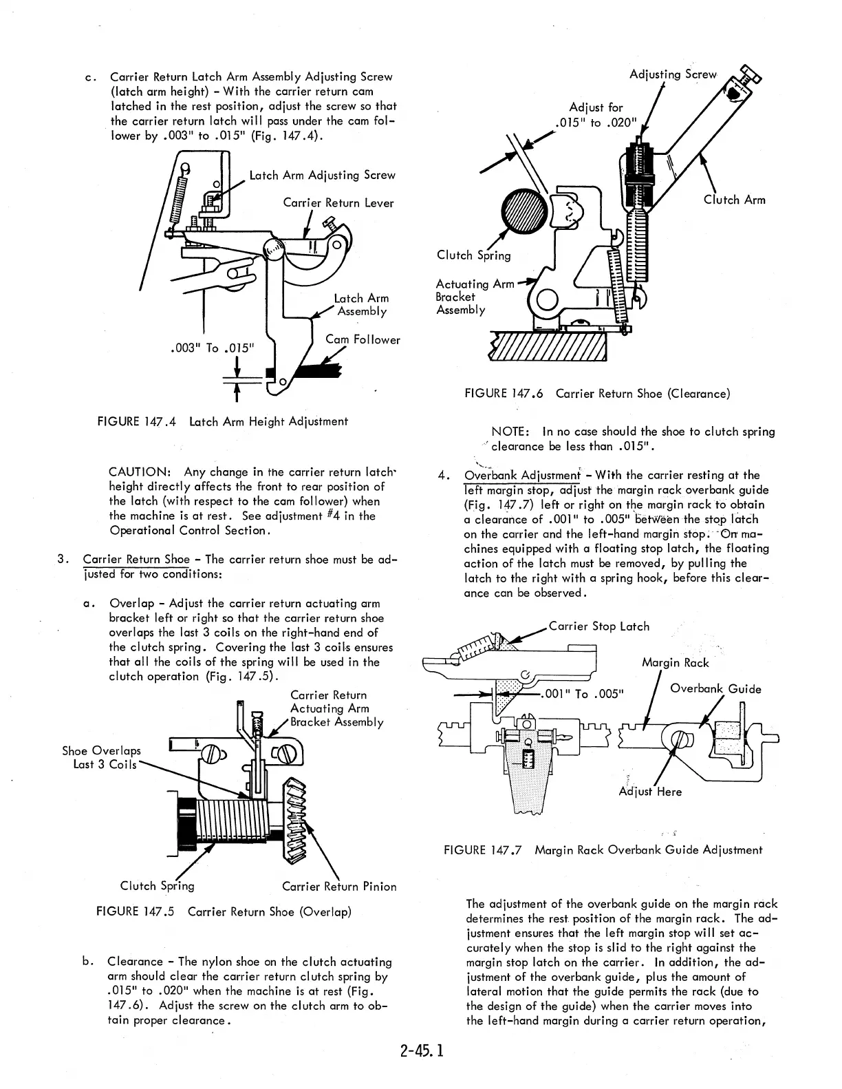
b.
Clearance
- The nylon shoe
on
the clutch
actuating
arm should
clear
the carrier return cl utch spring by
.015"
to
.020"
when the machine
is
at
rest (Fig.
147
.6).
Adjust the screw on the clutch
arm
to
ob-
tain
proper
clearance.
FIGURE
147.6
Carrier Return Shoe (Clearance)
"
NOTE:
In
no case should the shoe
to
clutch spring
..
!
clearance
be less than
.015".
4.
Ov';;;bank Adjustment - With the carrier resting
at
the
left margin
stop,
adjust the margin rack overbank guide
(Fig. 147.7) left or right on
t~e
margin
rackt6
obtain
a
clearance
of
.001"
to
.005"
beMeenthe
stojllatch
on the carrier and the
left-hand
margin sfop;
"Orr
ma-
chines equipped with a floating stop
latch,
the floating
action of the latch must
be
removed, by pulling the
latch
to
the right with a spring hook, before this
clear-
ance
can be observed.
2-45.1
Margin Rack
FIGURE
147.7
Margin Rack Overbank
Guide
Adjustment
The
adjustment of the overbank guide on the margin rcick
determines the rest. position
of
the margin
rack.
The
ad-
justment ensures
that
the left margin stop
wi
II
set
ac-
curately
when the stop
is
slid
to
the right against the
margin stop latch on the
carrier.
In
addition,
the
ad-
justment of the overbank
guide,
plus the amount of
lateral motion
that
the guide permits the rack (due
to
the design
of
the guide) when the carrier moves into
the
left-hand
margin during a carrier return
operation,