automatically
provides the carrier with the overbank
required for proper escapement pawl
re-entry
at
the
completion of a carrier return
operation.
5.
Clutch
Unlatching - With
either
style margin rack held
to
its extreme left position, the carrier return latch
keep-
er
should
clear
the latch by .005" to .015"
at
the
un-
latching point (Fig.
148).
Check
by manually holding
the
latch
at
the unlatching point whi
Ie
the machine
is
idling.
Lengthen or shorten the carrier return unlatching
I ink
to
obtain this
clearance.
NOTE: Should the clutch fail
to
properly latch (on
machines equipped with the
early
margin rack) after the
clutch unlatching adjustment has been completed,
check
the margin rack
eccentric
adjustment which
is
located
in the Margin
Control
section.
The
eccentric
may be
holding the rack too far to the left restricting the mar-
gin rack motion thereby reducing the amount of bite
that
the
latch
may take on the
keeper.
Margin Rack
Held
To
The
Left
---..
Latch Held Even
With The Keeper
Corner
FIGURE
148. Clutch Unlatching Adjustment
6;
Torque Limiter - The torque limiter should transmit 1 to
2 pounds pull on the carrier as
the
carrier
is
unlatching
the cl utch
at
the left margi
n.
If
a spring scale
is
available,
the adjustment may be
checked by holding against the carrier with the push end
of the scale and allowing the carrier
to
slowly unlatch
the
clutch
at
the left margin.
If
no scale
is
available,
the torque may be estimated by
holding the carrier while the
clutch
is
engaged.
The
torque limiter should slip
readily
yet return the carrier
positively without
any
hesitation when the carrier
is
re-
leased.
The adjustment
is
made by adjusting the
eccentric
stud
in
the torque limiter hub.
If
sufficient adjustment
is
not
available
at
the
eccentric,
the torque limiter spring may
be shifted on the torque limiter hub by positioning
the
torque limiter spring clamp.
NOTE: The carrier return
clutch
arbor should have an
end play
of
.004"
to
.006"
between the torque limiter
hub and the
C-clip
on the operational
shaft.
Adjust the
play by positioning the .torque limiter hub
laterally
on
the shaft. The end
play
can
be adjusted
easily
if
the
torque limiter spring
is
moved
to
the
right,
off the torque
limiter hub.
7.
Carrier Return Interlock
Contact
-
a.
Form
the
N/C
support so
that
the
O/P
lifts the
N/C
contact
.002"
to
.005"
(Fig. 149).
b.
Form
the
N/O
support so
that
the
O/P
clears the
N/O
contact
.035"
to
.045"
(Fig. 149).
N/C
Contact
.002"
to
.005"
(§)
Rise
O/p
N/O
Support
FIGURE
149.
Carrier Return Interlock Inactive
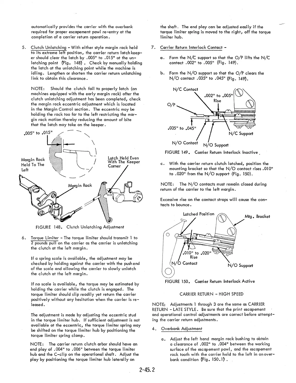
c.
With the carrier return
clutch
latched,
position the
mounting bracket
so
that
the
N/O
contact
rises
.010"
to
.020"
from
the
N/O
support (Fig. 150).
NOTE: The
N/O
contacts must remain closed during
return of the carrier
to
the left margin.
Excessive rise on the
contact
straps will cause the
con-
tacts to
bounce.
Mtg.
Bracket
o
.010"
to
.020"
~73I<§:;;;:J,
Rise
N/O
Contact
q)
FIGURE
150.
Carrier Return Interlock
Active
CARRIER
RETURN
- HIGH
SPEED
NOTE: Adjustments 1 through 3 are the same as
CARRIER
RETURN
-
LATE
STYLE.
Be
sure
that
the print escapement
and operational control adjustments
are
correcf
before
attempt-
ing the carrier return adjustments.
4.
Overbank Adjustment
a.
Adjust the left hand margin rack bushing to obtain
a
clearance
of
.002" to .004" between the working
surface
of
the escapement
pawl,
and the escapement
rack tooth with
the
carrier held to the left
in
an
over-
bank condition (Fig.
150.1)
•
2-45.2