Bushing
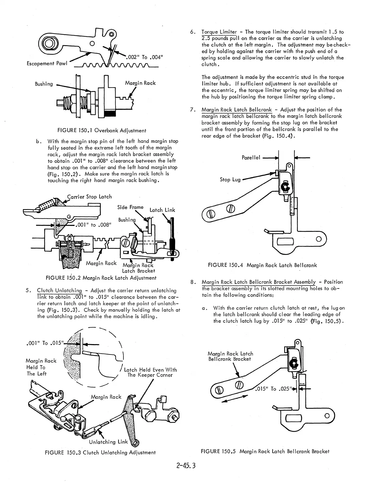
FIGURE 150.1
Overbank
Adjustment
b.
With
the
margin stop pin
of
the
left
hand margin stop
fully
seated
in
the
extreme left tooth
of
the
margin
rack,
adjust
the
margin
rack
latch
bracket
assembly
to
obtain
.001"
to
.008"
clearance
between
the
left
hand
stop on
the
carrier
and
the
left
hand margin stop
(Fig.
150.2).
Make
sure
the
margin
rack
latch
is
touching
the
right
hand margin
rack
bushing.
Bracket
FIGURE
150.2
Margin Rack Latch Adjustment
5.
Clutch
Unlatching - Adjust
the
carrier
return
unlatching
link
to
obtain
.001" to .015" clearanc;e
between
the
car-
rier
return
latch
and
latch
keeper
at
the
point
of
unlatch-
ing (Fig.
150.3).
Check
by manually holding
the
latch
at
the
unlatching
point
while
the
machine
is
idling.
FIGURE
150.3
Clutch
Unlatching Adjustment
6.
Torque Limiter - The torque limiter should transmit
1.5
to
2.5
pounds pull on
the
carrier
as
the
carrier
is
unlatching
the
clutch
at
the
left
margin.
The adjustment may
be
check-
ed
by
holding
against
the
carrier
with
the
push end
of
a
spring
scale
and allowing
the
carrier
to slowly
unlatch
the
clutch.
.
The adjustment
is
made by
the
eccentric
stud in
the
torque
limiter
hub.
If
sufficient
adjustment
is
not
available
at
the
eccentric,
the
torque I imiter spring may
be
sh
if
ted
on
the
hub by positioning
the
torque limiter spring
clamp.
7.
Margin Rack Latch Bellcrank - Adjust
the
position
of
the
margin
rack
latch
bellcrank
to
the
margin latch
bellcrank
bracket
assembly by forming
the
stop lug on
the
bracket
until
the
front portion
of
the
bellcrank
is
parallel
to
the
rear
edge
of
the
bracket
(Fig.
150.4).
FIGURE
150.4
Margin Rack Latch Bellcrank
8.
Margin Rack Latch Bellcrank Bracket Assembly - Position
the
bracket
assembly in its
slotted
mounting holes to
ob-
tain
the
following conditions:
a.
With
the
carrier
return
clutch
latch
at
rest,
the lug on
the
latch
bellcrank
should
clear
the
leading
edge
of
the
clutch
latch
lug by .015" to .025" '(Fig.
150.5).
FIGURE
150.5
Margin Rack Latch Bellcrank Bracket
2-45.3