b.
Hand
cycle
a
carrier
return
operation.
With the
clutch
latch
moving through its
arc,
the
lug on
the
clutch
latch
should
engage
the
lug on
the
latch
bell-
crank
by
the
thickness
of
the
metal
of
the
latch
bell-
crank
lug
(Fig.
150.6) .
Engage The Thickness
Of
Metal
FIGURE
150.6 Margin Rack Latch Bellcrank Bracket
NOTE: Increased motion
of
the margin
rack
latch
bellcrank
may
be
obtained
by increasing
the
engage-
ment
of
the
lugs.
9.
Margin Rack Latch Link - Adjust
the
margin
rack
latch
I ink to el
iminate
lost motion in the mechanism when
the
machine
is
at
rest
and
the
margin
rack
is
latched.
10.
Carrier
Return
Clutch
Latch Keeper - The
clutch
latch
keeper
stop should
be
adjusted
to I imit
the
engagement
of
the
keeper
with
the
clutch
latch
to .040"
(Fig.
150.7) .
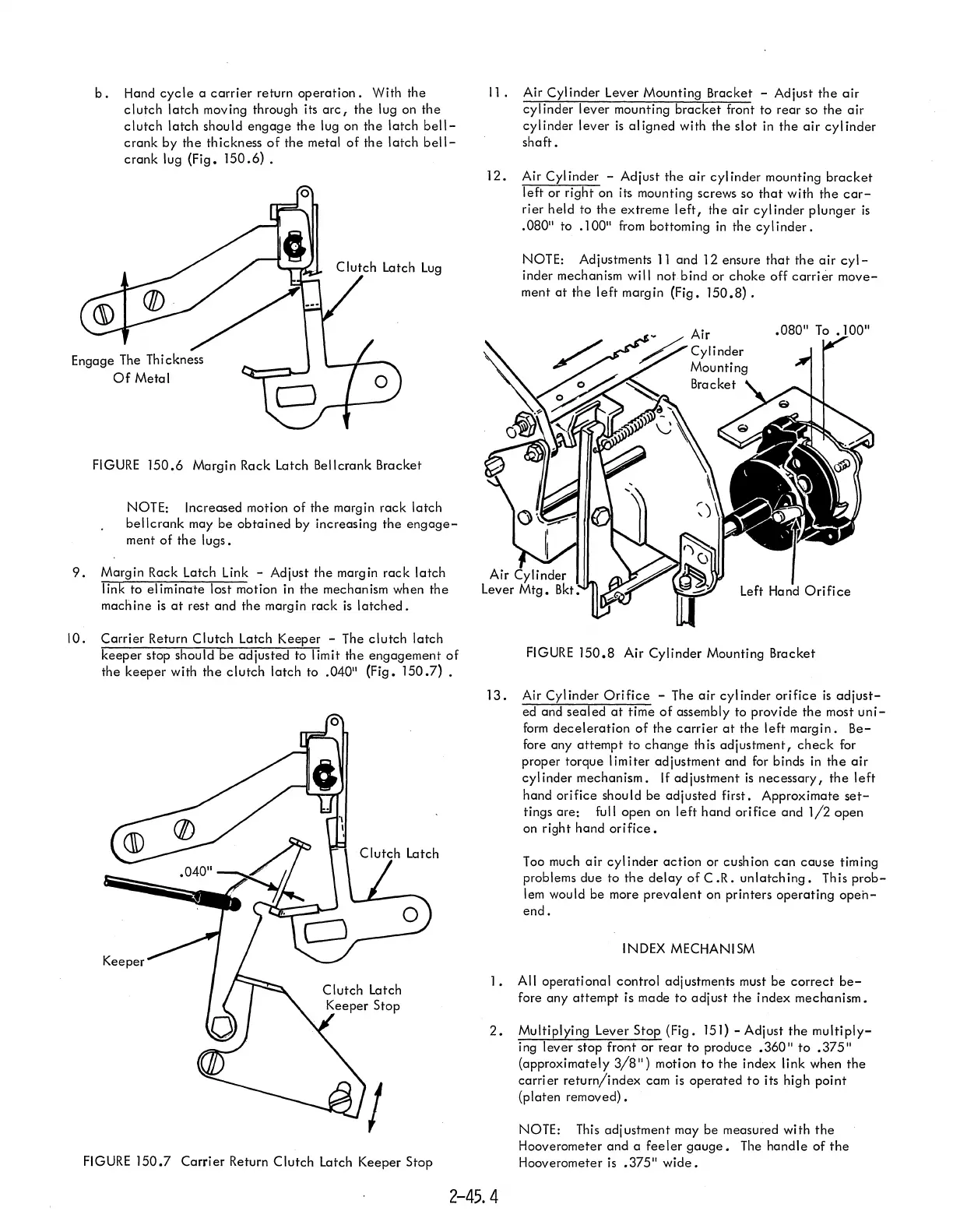
11. Air
Cylinder
Lever Mounting Bracket - Adjust
the
air
cyl inder
lever
mounting
bracket
front
to
rear
so
the
air
cylinder
lever
is
aligned
with
the
slot
in
the
air
cylinder
shaft.
12. Air Cyl inder - Adjust
the
air
cyl inder mounting
bracket
left
or
right
on its mounting screws so
that
with
the
car-
rier
held
to
the
extreme
left,
the
air
cylinder
plunger
is
.080" to .100" from bottoming
in
the
cyl
inder.
NOTE: Adjustments
11
and
12 ensure
that
the
air
cyl-
inder mechanism will
not
bind
or
choke
off
carrier
move-
ment
at
the
left
margin (Fig.
150.8).
FIGURE
150.8
Air
Cylinder
Mounting Bracket
13.
Air
Cylinder
Orifice
- The
air
cylinder
orifice
is
adjust-
ed and
sealed
at
time
of
assembly to
provide
the
most
uni-
form
deceleration
of
the
carrier
at
the
left
margin.
Be-
fore any
attempt
to
change
th
is
adjustment,
check
for
proper torque
limiter
adjustment
and
for binds
in
the
air
cylinder
mechanism.
If
adjustment
is
necessary,
the
left
hand
orifice
should be
adjusted
first.
Approximate
set-
tings
are:
full
open
on
left
hand
orifice
and
1/2
open
on right
hand
orifice.
Too much
air
cylinder
action
or cushion
can
cause
timing
problems
due
to
the
delay
of
C.R.
unlatch
ing.
This
prob-
lem would be more
prevalent
on
printers
operating
opeh-
end.
INDEX MECHANISM
1.
All
operational
control
adjustments must be
correct
be-
fore
any
attempt
is made
to
adjust
the
index
mechanism.
2.
Multiplying Lever
Stop
(Fig.
151)
- Adjust
the
multiply-
ing
lever
stop front
or
rear
to
produce .360"
to
.375"
(approximately
3/8")
motion
to
the
index link
when
the
carrier
return/index
cam
is
operated
to
its high
point
(platen
removed).
NOTE: This
adjustment
may be measured
with
the
Hooverometer
and
a
feeler
gauge.
The
handle
of
the
FIGURE 150.7
Carrier
Return
Clutch
Latch
Keeper
Stop Hooverometer
is
.375"
wide.
2-45.4