8.
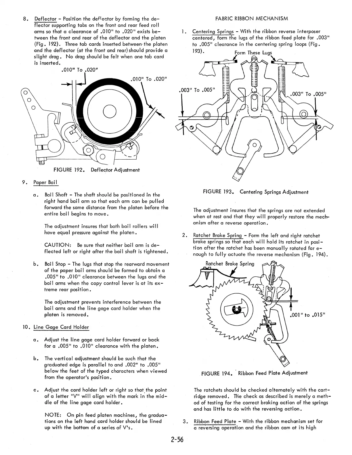
Deflector - Position
the
def1e.;:tor by forming
the
de-
flector
supporting tabs on
the
front and
rear
feed roll
arms so
that
a
clearance
of
.010" to .020" exists
be-
tween
the
front
and
rear
ofthe
deflector
and
the
platen
(Fig.
192). Three
tab
cards inserted between·
the
platen
and
the
deflector
(at
the
front and rear) should provide a
slight
drag.
No
drag should be
felt
when one
tab
card
is
inserted •
• 010"
To
.020"
FIGURE
192. Deflector Adjustment
9.
Paper
Bai
I
a.
Bail
Shaft -
The
shaft should be positioned in
the
right hand bai I arm so
that
each
arm
can
be
pulled
forward
the
same
distance
from
the
platen
before
the
entire
bail begins to move.
The adjustment insures
that
both bai I rollers
wi
II
have equal pressure against the
platen.
CAUTION:
Be
sure
that
neither bail arm
is
de-
flected
left
or
right
after
the
bai I shaft
is
tightened.
b.
Bai
I Stop - The lugs
that
stop
the
rearward movement
of
the
paper bail arms should be formed to obtain a
.005"
to
.010"
clearance
between
the
lugs and
the
bai I arms when
the
copy control lever
is
at
its
ex-
treme
rear
position.
The
adjustment prevents interference between
the
bai I arms
and
the
Ii ne
gage
card holder when
the
platen
is
removed.
JO.
Line
Gage
Card Holder
a.
Adjust
the
line
gage
card holder forward
or
back
for a .005"
to
.010"
clearance
with
the
platen.
b.
The
verti
ca
I adjustment shou
Id
be such
that
the
graduated
edge
is
parallel
to and .002" to .005"
below
the
feet
of
the
typed characters when
viewed
from
the
operator's
position.
c.
Adjust
the
card
holder left or right so
that,the
point
of
a
letter
"V" will
align
with
the
mark in
the
mid-
dle
of
the
line
gage
card
holder.
NOTE:
On
pin feed
platen
machines,
the
gradua-
tions on
the
left hand card holder should be lined
up with
the
bottom
of
a series
of
V's.
FABRIC
RIBBON
MECHANISM
I.
Centering Springs - With
the
ribbon reverse interposer
centered,
form
the
lugs
of
the
ribbon feed
plate
for .003"
to
.005"
clearance
in the centering spring loops
(Fig.
193).
Form
These lugs .
FIGURE
193. Centering Springs Adjustment
The
adjustment insures
that
the springs
are
not
extended
when
at
rest and
that
they
wi
II
properly restore
the
mech-
anism
after
a reverse
operation.
2.
Ratchet Brake Spring -
Form
the
left and right
ratchet
brake springs so
that
each
wi
II
hold its
ratchet
in
posi-
tion
after
the
ratchet
has been manually
rotated
far
e-
nough
to
fully
actuate
the
reverse mechanism (Fig. 194).
Ratchet Brake Spring
I
.001"
to
.015"
FIGURE
194. Ribbon Feed Plate Adjustment
The
ratchets should be
checked
alternately
with
the
cart-
ridge removed.
The
check
as described
is
merely
a
meth-
od of testing for
the
correct braking
action
of
the
springs
and
has
little
to do with
the
reversing
action.
3.
Ribbon Feed Plate - With
the
ribbon mechanism
set
for
a reversing operation and
the
ribbon cam
at
its high
2-56