EasyManuals Logo

IBM StorVize V7000 Gen2+ User Manual

IBM StorVize V7000 Gen2+
188 pages
To Next Page IconTo Next Page
To Previous Page IconTo Previous Page
Page #108 background imageLoading...
Page #108 background image
Remove the bottom (1U) fascia
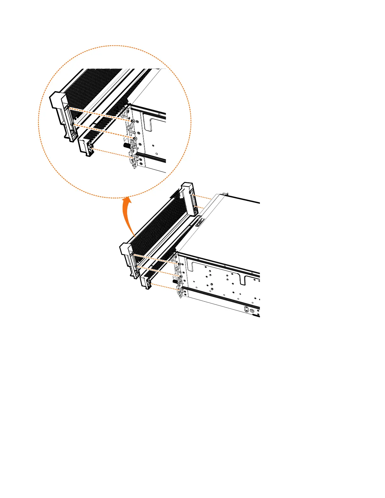
3. Gently pull on each side of the PSU fascia to remove it from the chassis, as
shown in Figure 76. The PSU fascia will disengage from the slot and pin that
connect it to each side of the chassis
You must remove the bottom fascia to access and service either PSU. However,
as Figure 77 on page 85 shows, you do not have to remove the front fascia.
svc01043
Figure 76. Remove fascia components from the expansion enclosure
84 Storwize V7000 Gen2 and Gen2+: Quick Installation Guide

Table of Contents

Questions and Answers:

Question and Answer IconNeed help?

Do you have a question about the IBM StorVize V7000 Gen2+ and is the answer not in the manual?

IBM StorVize V7000 Gen2+ Specifications

General IconGeneral
ModelStorwize V7000 Gen2+
Storage TypeHybrid Flash Array
RAID LevelsRAID 0, 1, 5, 6, 10
Form Factor2U
Operating SystemIBM Spectrum Virtualize
Drive Types SupportedSSD
Host Interface8/16 Gbps Fibre Channel, 1/10 Gbps iSCSI
Cache Memory64 GB per control enclosure
Nodes2 nodes per control enclosure
Processor Cores8-core processor per node
ConnectivityFibre Channel, iSCSI

Related product manuals