EasyManuals Logo

IBM StorVize V7000 Gen2+ User Manual

IBM StorVize V7000 Gen2+
188 pages
To Next Page IconTo Next Page
To Previous Page IconTo Previous Page
Page #32 background imageLoading...
Page #32 background image
Expansion enclosure components
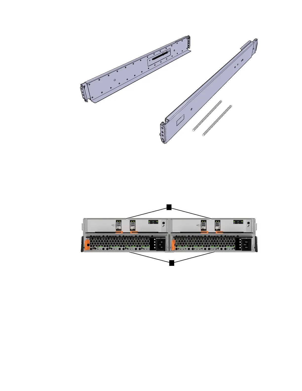
Figure 4 shows the location of the power supply units and expansion canisters.
v 1 Expansion canisters
v 2 Power supply units
Figure 5 on page 9 shows the LEDs and SAS port locations from the rear view of
an expansion canister.
v 1 LEDs
v 2 SAS ports
Each canister has two SAS ports that are numbered 1 on the left and 2 on the right.
Port 1 is used to connect to a SAS expansion port on a node canister or port 2 of
another expansion canister.
fab10051
Figure 3. Control enclosure support rails of a Storwize V7000 system
fab10006
2
1
IN
DC
!
OK
IN
DC
!
OK
Figure 4. Rear view of a Storwize V7000 expansion enclosure
8 Storwize V7000 Gen2 and Gen2+: Quick Installation Guide

Table of Contents

Questions and Answers:

Question and Answer IconNeed help?

Do you have a question about the IBM StorVize V7000 Gen2+ and is the answer not in the manual?

IBM StorVize V7000 Gen2+ Specifications

General IconGeneral
ModelStorwize V7000 Gen2+
Storage TypeHybrid Flash Array
RAID LevelsRAID 0, 1, 5, 6, 10
Form Factor2U
Operating SystemIBM Spectrum Virtualize
Drive Types SupportedSSD
Host Interface8/16 Gbps Fibre Channel, 1/10 Gbps iSCSI
Cache Memory64 GB per control enclosure
Nodes2 nodes per control enclosure
Processor Cores8-core processor per node
ConnectivityFibre Channel, iSCSI

Related product manuals