EasyManuals Logo

IBM StorVize V7000 Gen2+ User Manual

IBM StorVize V7000 Gen2+
188 pages
To Next Page IconTo Next Page
To Previous Page IconTo Previous Page
Page #158 background imageLoading...
Page #158 background image
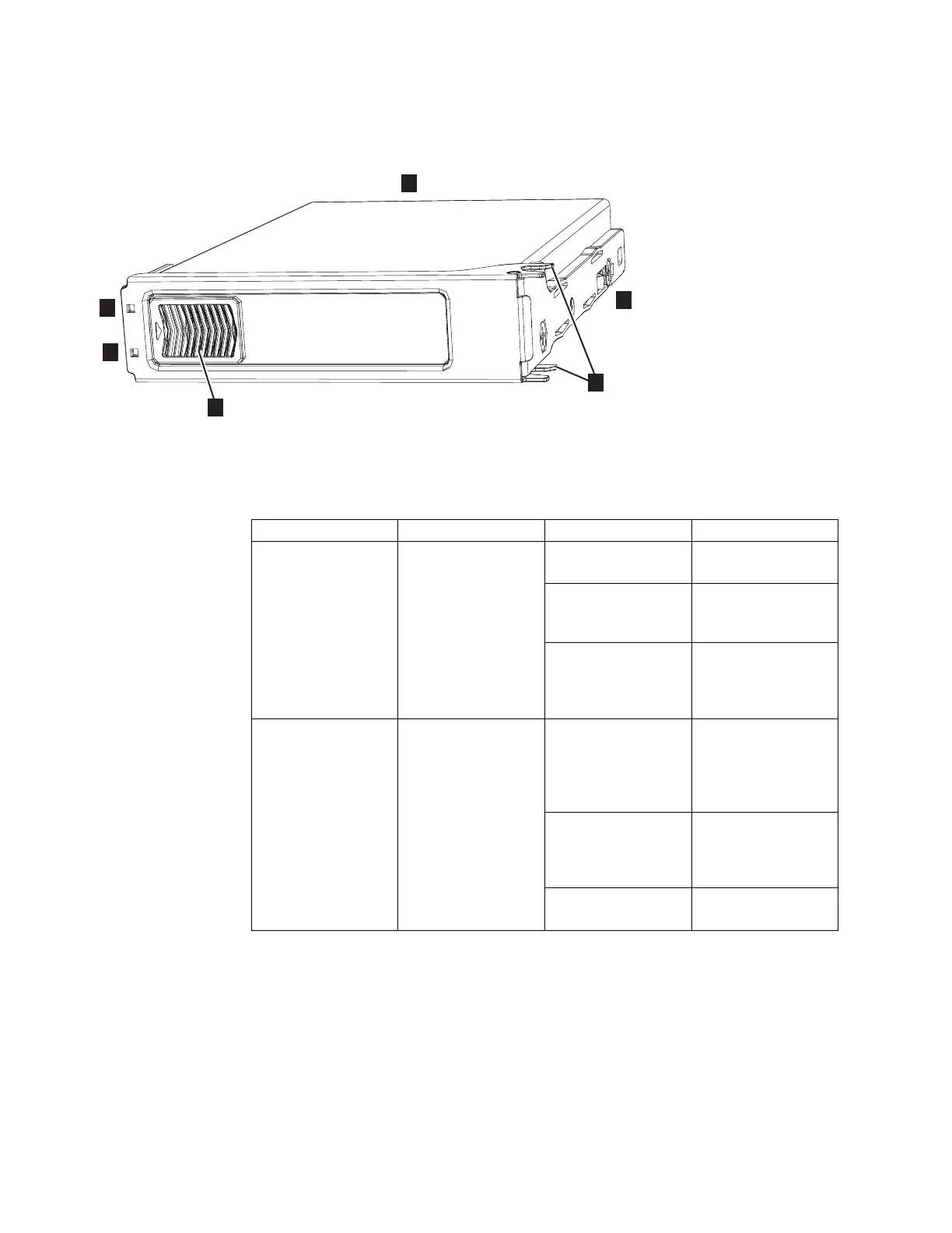
Figure 122 shows the components of a drive assembly. Each drive has an online
indicator (2) and fault indicator (3).
Table 17 describes the meaning of the LEDs on each drive.
Table 17. LED indicators on drives
Function Color Status Description
2 Activity Green On The drive is ready to
be used.
Flashing The drive is
operating and I/O is
occurring.
Off The drive is not
installed or an
installed drive is not
ready to be used.
3 Fault Amber On A fault occurred on
the drive. The LED is
turned off when the
drive is removed and
replaced.
Flash The drive is being
identified; a fault
might or might not
be detected.
Off The installed drive is
operating normally.
Figure 123 on page 135 shows the LEDs on a secondary expansion module.
1
2
3
6
svc01056
4
5
Figure 122. LEDs on a drive assembly
134 Storwize V7000 Gen2 and Gen2+: Quick Installation Guide

Table of Contents

Questions and Answers:

Question and Answer IconNeed help?

Do you have a question about the IBM StorVize V7000 Gen2+ and is the answer not in the manual?

IBM StorVize V7000 Gen2+ Specifications

General IconGeneral
ModelStorwize V7000 Gen2+
Storage TypeHybrid Flash Array
RAID LevelsRAID 0, 1, 5, 6, 10
Form Factor2U
Operating SystemIBM Spectrum Virtualize
Drive Types SupportedSSD
Host Interface8/16 Gbps Fibre Channel, 1/10 Gbps iSCSI
Cache Memory64 GB per control enclosure
Nodes2 nodes per control enclosure
Processor Cores8-core processor per node
ConnectivityFibre Channel, iSCSI

Related product manuals