EasyManuals Logo

IBM StorVize V7000 Gen2+ User Manual

IBM StorVize V7000 Gen2+
188 pages
To Next Page IconTo Next Page
To Previous Page IconTo Previous Page
Page #88 background imageLoading...
Page #88 background image
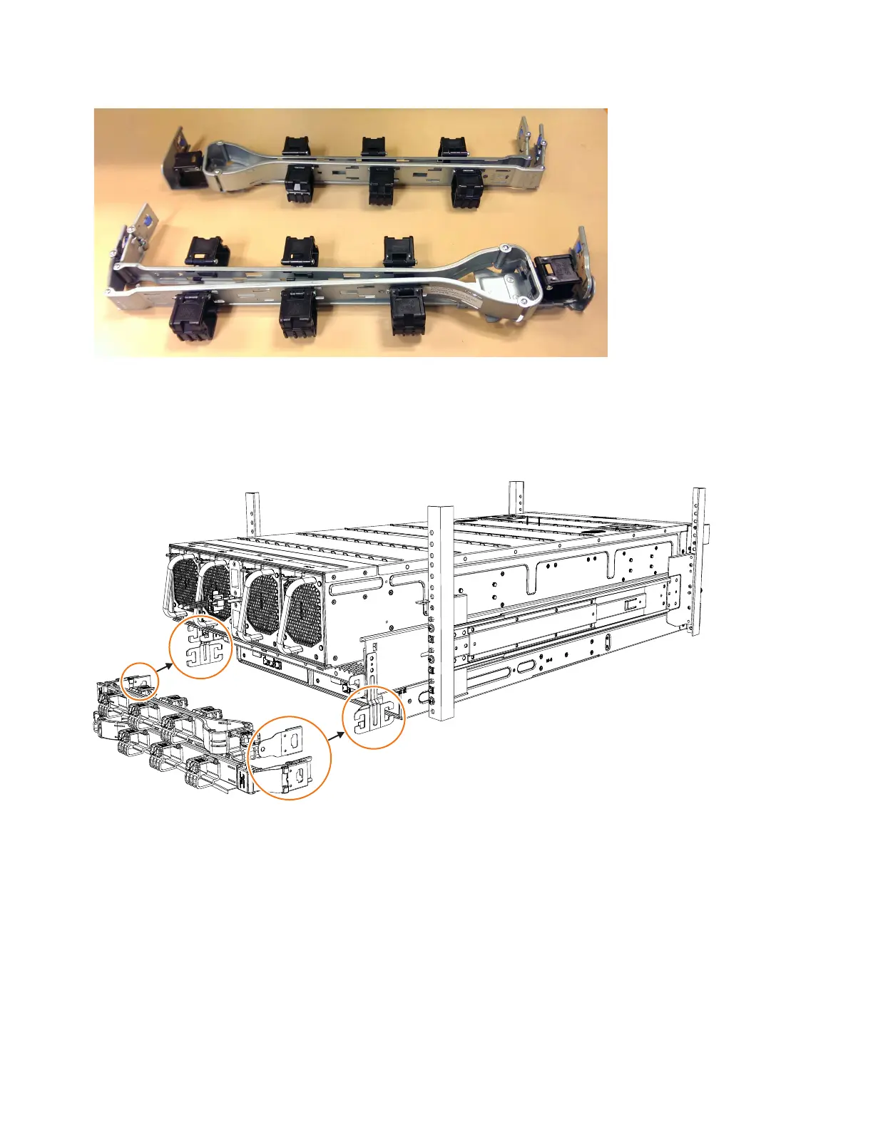
As Figure 52 shows, the support rail connectors of each CMA assembly are
installed on the rail hooks at the end of the support rails.
Procedure
1. Remove the loop straps from the upper and lower CMA assemblies. The straps
are used only for shipping.
Installing the upper CMA assembly
Figure 53 on page 65 shows the connectors on the upper CMA assembly.
svc01017
Figure 51. Upper and lower cable-management arms
svc00974
Figure 52. Upper and lower cable-management arms
64 Storwize V7000 Gen2 and Gen2+: Quick Installation Guide

Table of Contents

Questions and Answers:

Question and Answer IconNeed help?

Do you have a question about the IBM StorVize V7000 Gen2+ and is the answer not in the manual?

IBM StorVize V7000 Gen2+ Specifications

General IconGeneral
ModelStorwize V7000 Gen2+
Storage TypeHybrid Flash Array
RAID LevelsRAID 0, 1, 5, 6, 10
Form Factor2U
Operating SystemIBM Spectrum Virtualize
Drive Types SupportedSSD
Host Interface8/16 Gbps Fibre Channel, 1/10 Gbps iSCSI
Cache Memory64 GB per control enclosure
Nodes2 nodes per control enclosure
Processor Cores8-core processor per node
ConnectivityFibre Channel, iSCSI

Related product manuals