EasyManuals Logo

IBM StorVize V7000 Gen2+ User Manual

IBM StorVize V7000 Gen2+
188 pages
To Next Page IconTo Next Page
To Previous Page IconTo Previous Page
Page #113 background imageLoading...
Page #113 background image
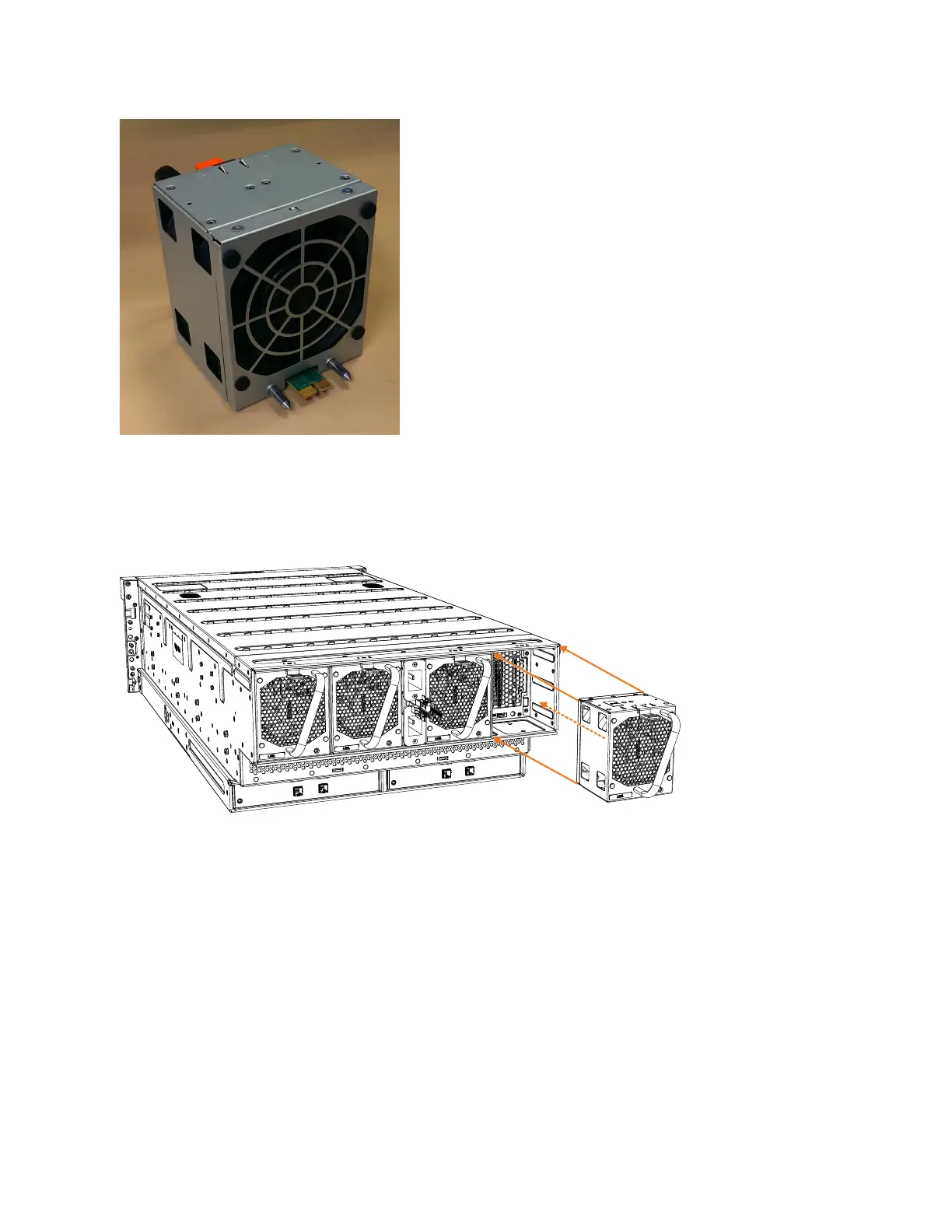
2. Carefully insert the fan module into the chassis until it clicks in place, as shown
in Figure 82.
Replacing all fan modules
3. Repeat steps 1 on page 88 and 2 for each fan module to be replaced.
4. Power on the expansion enclosure.
Installing or replacing a fan interface board: 2076-92F
You can replace a fan interface board (FIB) in a 2076-92F expansion enclosure.
Before you begin
This task assumes that the following conditions are met:
v You have removed the fan interface board, following the process described in
“Removing a fan interface board: 2076-92F” on page 113.
v All power cables were removed from the enclosure, as described in “Powering
off the expansion enclosure: 2076-92F” on page 130.
svc01016
Figure 81. Fan module orientation
svc01048
Figure 82. Replace fan module
Chapter 2. Installing the Storwize V7000 Gen2 and Storwize V7000 Gen2+ hardware 89

Table of Contents

Questions and Answers:

Question and Answer IconNeed help?

Do you have a question about the IBM StorVize V7000 Gen2+ and is the answer not in the manual?

IBM StorVize V7000 Gen2+ Specifications

General IconGeneral
ModelStorwize V7000 Gen2+
Storage TypeHybrid Flash Array
RAID LevelsRAID 0, 1, 5, 6, 10
Form Factor2U
Operating SystemIBM Spectrum Virtualize
Drive Types SupportedSSD
Host Interface8/16 Gbps Fibre Channel, 1/10 Gbps iSCSI
Cache Memory64 GB per control enclosure
Nodes2 nodes per control enclosure
Processor Cores8-core processor per node
ConnectivityFibre Channel, iSCSI

Related product manuals