Conversely, the overall weight of the expansion enclosure is reduced as you
remove parts. However, even with parts removed, the 2076-92F expansion
enclosure is heavy. Depending on the number of parts that remain, you might need
four persons or a mechanical lift to support the weight of the expansion enclosure.
Identify the hardware components: 2076-92F
You should become familiar with the external components of the 2076-92F
expansion enclosure.
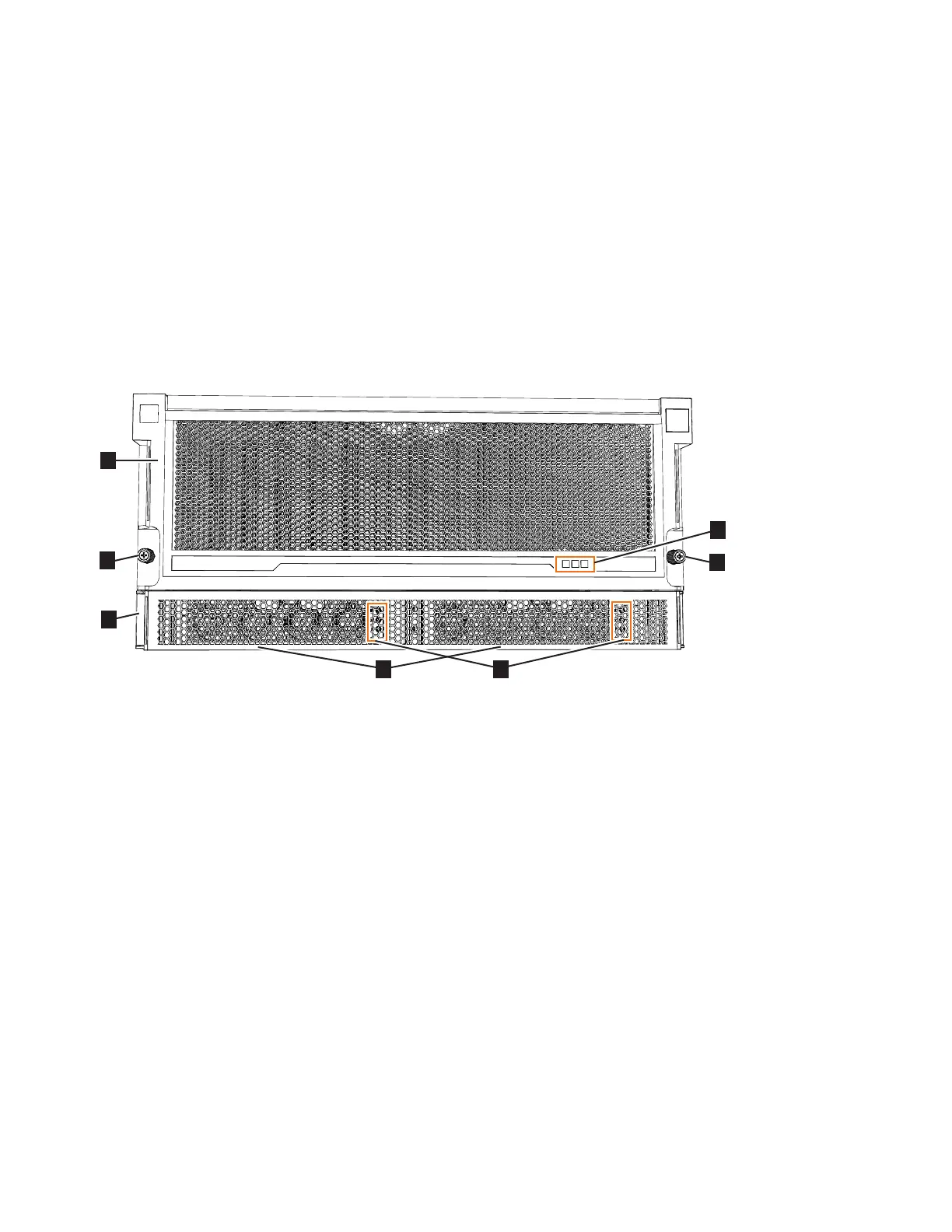
Components on the front of the enclosure
Figure 24 shows the front of the 2076-92F expansion enclosure. In the figure, all
parts are installed in the enclosure.
▌1▐ Display panel indicators
▌2▐ Rack retention thumb screws
▌3▐ Power supply unit indicators
▌4▐ Power supply units (PSUs)
▌5▐ PSU fascia (1U)
▌6▐ Front fascia (4U)
However, as Figure 25 on page 39 shows, the 4U and 1U fascias are packaged
separately. You must attach them to the front of the 2076-92F expansion enclosure
as part of the initial installation process.
Figure 24. Features on the front of the 2076-92F expansion enclosure
38 Storwize V7000 Gen2 and Gen2+: Quick Installation Guide