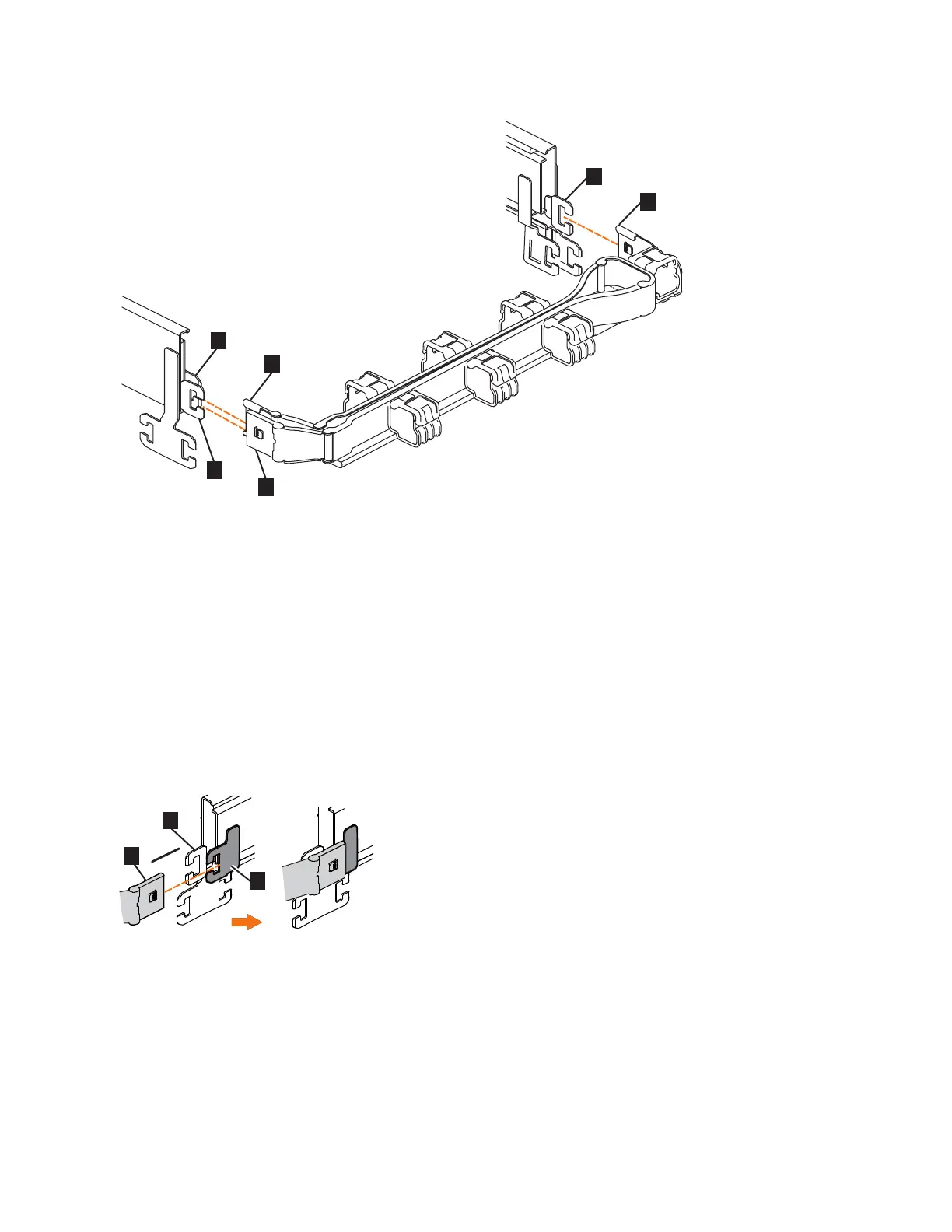
▌1▐ Inner connector on upper CMA
▌2▐ Connector base on inner rail member
▌3▐ Outer connector on upper CMA
▌4▐ Connector base on outer rail member
▌5▐ Support rail connector on upper CMA
▌6▐ Connector base on outer rail member
2. Install the inner connector of the upper CMA assembly (▌1▐) to the inner
member of the left support rail (▌2▐), as shown in Figure 54 from the outer and
inner support rails.
3. Install the inner connector of the upper CMA assembly (▌3▐) to the inner
member of the left support rail (▌4▐), as shown in Figure 55 on page 66.
Figure 53. Connectors for the cable management arm
Figure 54. Install the inner connector of the upper CMA to the inner member of the support rail
Chapter 2. Installing the Storwize V7000 Gen2 and Storwize V7000 Gen2+ hardware 65