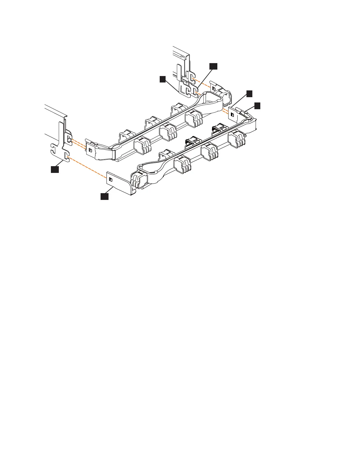
▌7▐ Inner connector on lower CMA
▌8▐ Connector base on inner rail member
▌9▐ Outer connector on lower CMA
▌10▐ Connector base on outer rail member
▌11▐ Support rail connector the lower CMA
▌12▐ Connector base on outer rail member
5. Install the inner connector of the lower CMA assembly (▌7▐) to the inner
member of the right support rail (▌8▐), as shown in Figure 57).
6. Install the outer connector of the lower CMA assembly (▌9▐) to the outer
member of the right support rail ▌10▐, as shown in Figure 57.
7. Attach the support rail connector on the lower CMA assembly (▌11▐) to the
connector on the left support rail (▌12▐), as shown in Figure 57. Ensure the
lower CMA assembly is securely attached to the hooks on the end of the
support rails.
8. Route the cables and power cords on the CMA. If needed, secure them with
cable ties or hook-and-loop fasteners.
Notes:
v Use the cable straps that are provided on the rear of the system to retain the
cables and prevent them from sagging.
v Allow slack in all of the cables to avoid tension in the cables as the CMA
moves.
9. Reconnect the power cords and other cables, as needed.
Figure 57. Comparing the location of the components of the CMA assemblies
Chapter 2. Installing the Storwize V7000 Gen2 and Storwize V7000 Gen2+ hardware 67