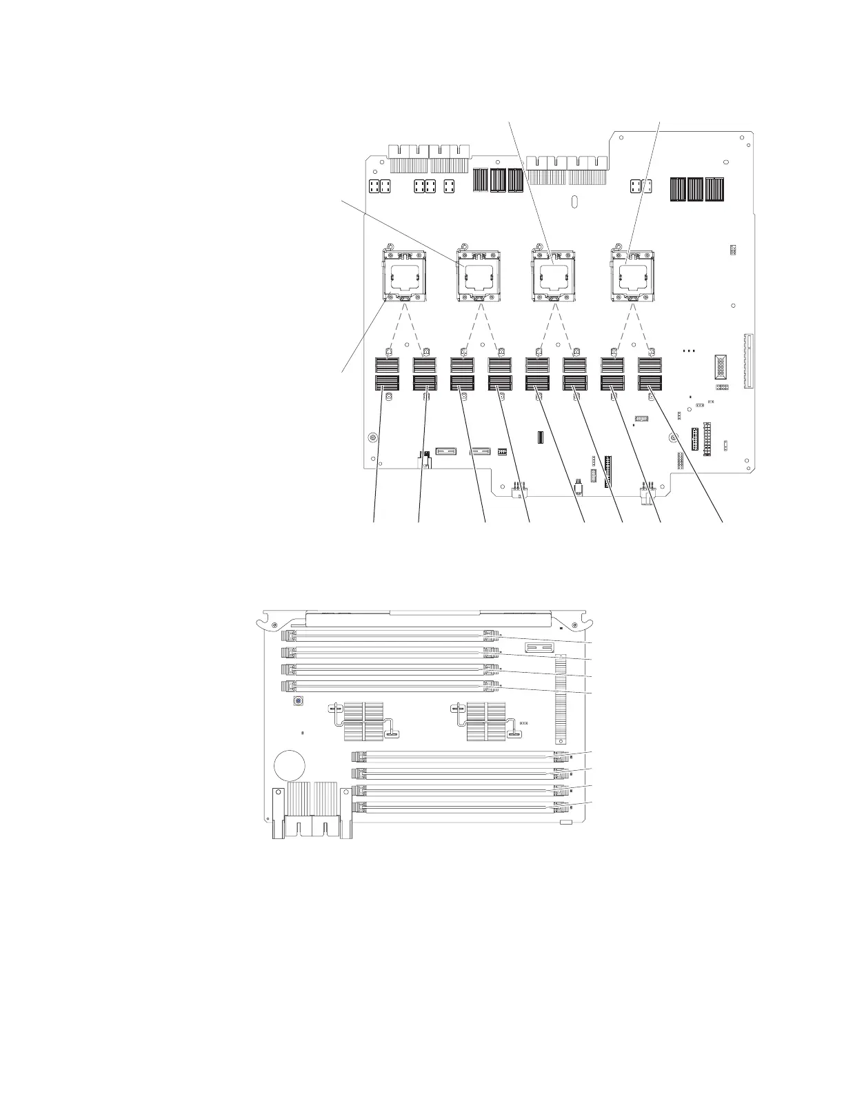
Memory
card 1
Memory
card 2
Memory
card 3
Memory
card 4
Memory
card 5
Memory
card 6
Memory
card 7
Memory
card 8
Microprocessor 1
connector
Microprocessor 2
connector
Microprocessor 3
connector
Microprocessor 4
connector
Front of server
v The following illustration shows the DIMM connectors on a memory card.
DIMM 1
DIMM 2
DIMM 3
DIMM 4
DIMM 5
DIMM 6
DIMM 7
DIMM 8
v In a low-cost and low-power DIMM installation, install the DIMMs on each
memory card in the order shown in the following tables. The goal in a low-cost
and low-power configuration is to completely fill each memory card before you
install the next memory card.
Chapter 5. Removing and replacing components 131
 Loading...


