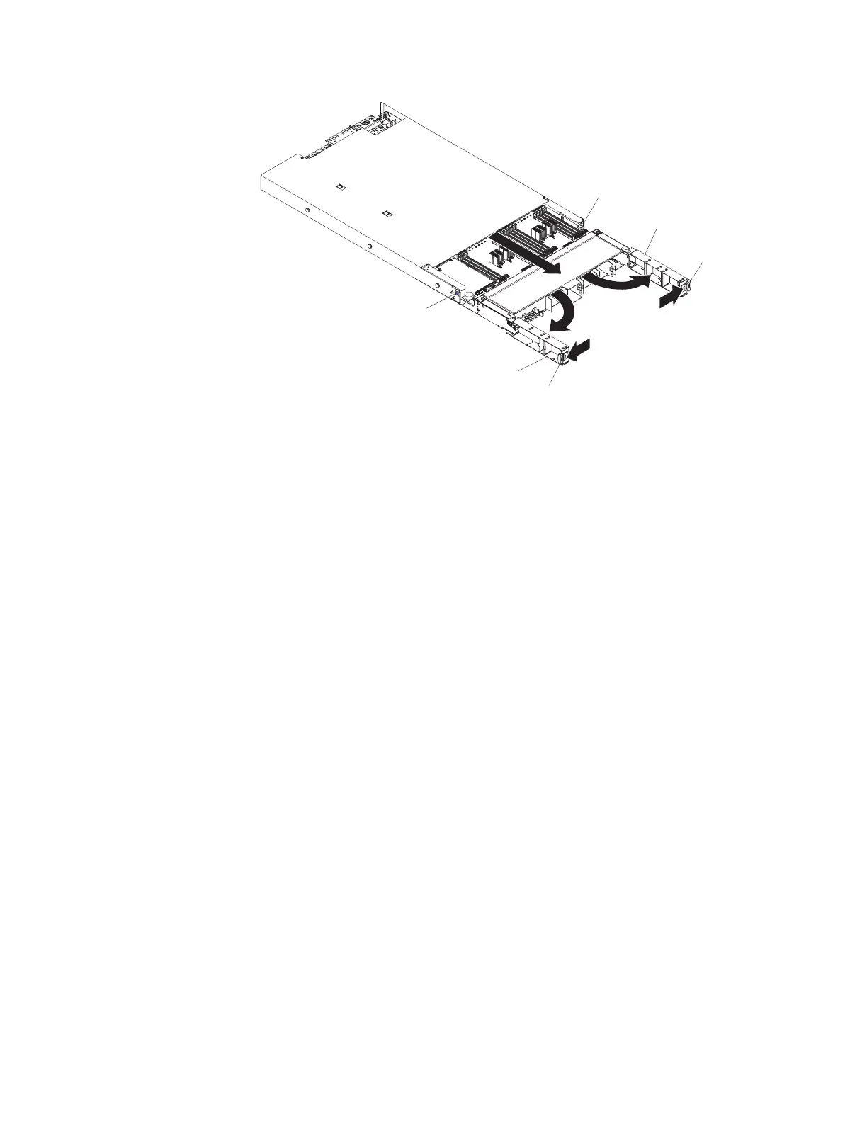
Stop-tab
Release latch
Release latch
Stop-tab
Handle
Handle
6. Grasp the handles and pull the system-board tray out until it stops; then,
press inward on the stop-tabs on both sides of the system-board tray and pull
the tray out of the chassis.
7. Remove the air baffle (see “Replacing the memory expansion module air
baffle” on page 180).
8. Remove the DIMMs (see “Removing a memory expansion module DIMM” on
page 185).
9. Remove all hot-swap fans (see “Removing a memory expansion module
hot-swap fan” on page 183).
10. If you are instructed to return the system-board tray, follow all packaging
instructions, and use any packaging materials for shipping that are supplied
to you.
Replacing the memory expansion module system-board tray
assembly
This topic provides instructions for how to replace the system-board tray.
About this task
Note:
1. When you replace the system-board tray in the memory expansion module, be
sure to order the correct system-board tray for your model. A label comes on
models of the memory expansion module that contain the Intel 7510 scalable
memory buffer. The label is located on top of the system-board tray. A note on
the label states "This MAX5 contains Intel 7510 scalable memory buffer". In
addition, models of the memory expansion module that contain the Intel 7510
scalable memory buffer will have a label attached inside of the memory
expansion module chassis. To locate the label, remove the front bezel. The label
is attached to the left side of the chassis and states "7510 SMP". See the parts
listing table in “Replaceable memory expansion module components” on page
90 for more information about the correct system-board tray for your model.
2. When you reassemble the components in the memory expansion module, be
sure to route all cables carefully so that they are not exposed to excessive
pressure.
3. When you replace the system-board tray, make sure that the host UEFI
firmware is at the latest level (see “Updating the firmware” on page 201).
198 IBM System x3850 X5 and x3950 X5 Types 7145, 7146, 7143, and 7191: Problem Determination and Service Guide
 Loading...


