prox.pad Installation/Programming Manual
1.15 Checking the Cables
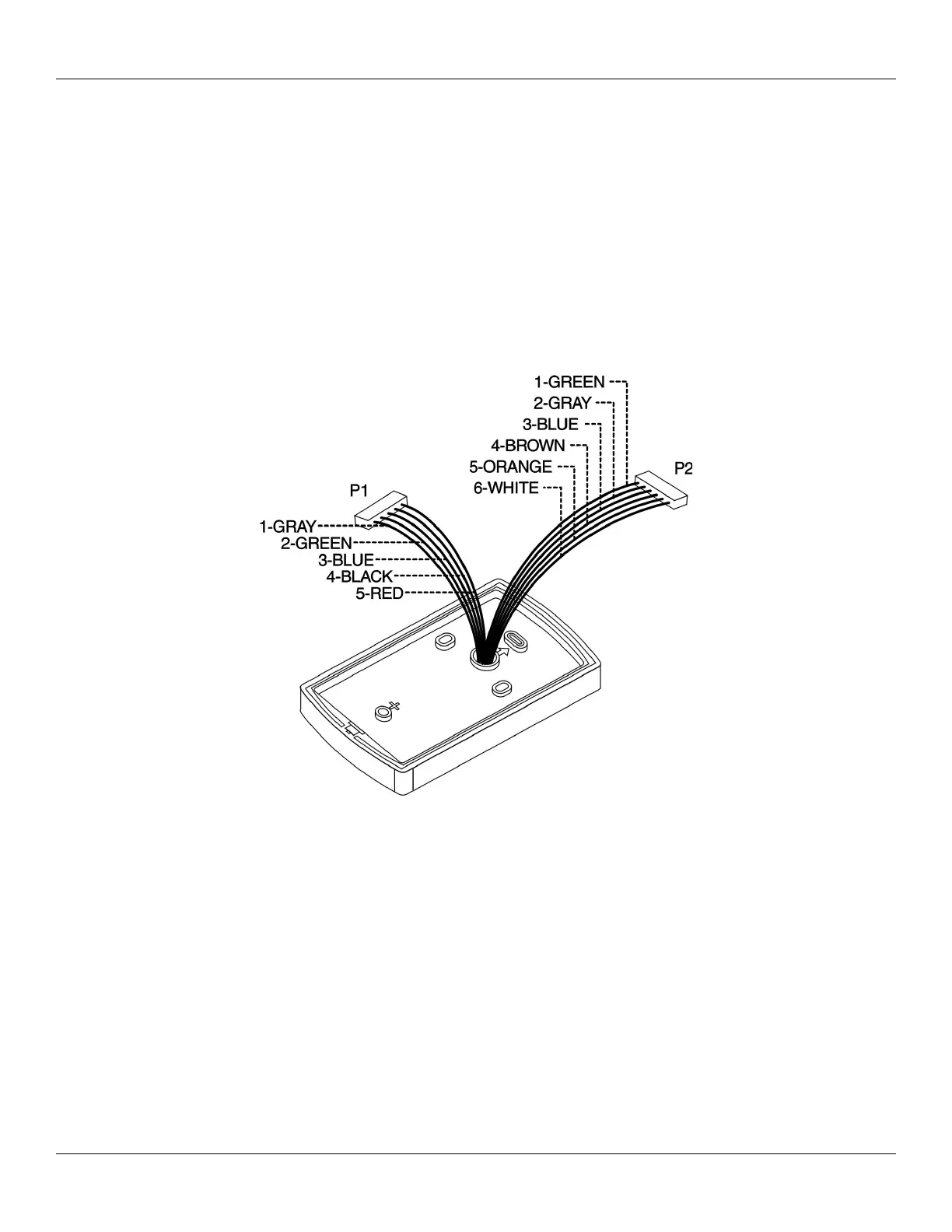
Figure 1 below provides a detailed illustration of the prox.pad’s wiring harness. Figure 2 illustrates the pin connectors on the main
circuit board; Table 2 describes these four Pin connectors, P1, P2, P3, and P4.
Document # 6055676, Rev 2.2, D4b Page 15 of 86
Figure 1: prox.pad Wiring Harness

 Loading...