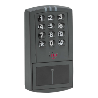
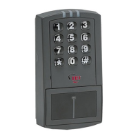
prox.pad Installation/Programming Manual
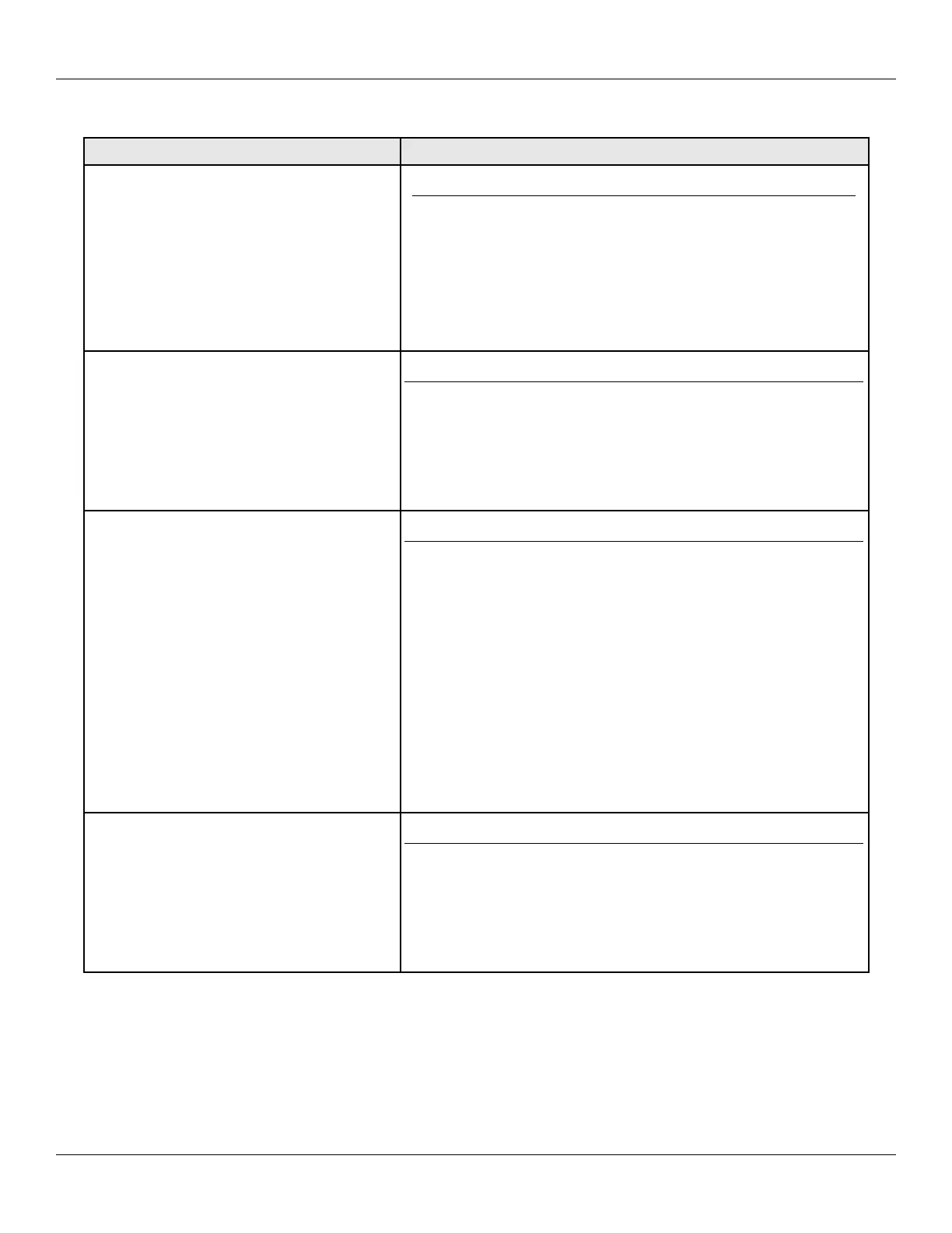
Table 2: prox.pad Pin Connectors
Pin Connector (on main circuit board) Description/Use
P1 (5-pin connector, top left-most location)
Pin Wire Color Use
1 Gray Main Relay Normally Closed
2 Green Main Relay Normally Open
3 Blue Main Relay Common
4 Black Ground (Power Supply)
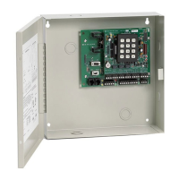
5 Red +12V Input (Power Supply)
P3 (4-pin connector, top middle location)
Pin Wire Color Use
1 Blue Not Used
2 Brown Wiegand LED Control
3 White Wiegand Data 1 (SS White/Yellow)
4 Green Wiegand Data 0 (SS White/Black)
P2 (6-pin connector, top right-most location)
Pin Wire Color Use
1 Green Aux Relay Normally Open
2 Gray Aux Relay Normally Closed
3 Blue Aux Relay Common
4 Brown REX Loop
5 Orange Door Contact Loop
6 White Loop Common
NOTE: Pins 1, 2, 3 can be wired at the installer’s option for one of
the following alarm outputs, Alarm Shunt, Forced Door, or
Propped Door. Mandatory: If you are not installing door contacts
per Figure 12, twist the white and orange wires together. If not
done, the REX input won't work.
P4 (4-pin connector, bottom location)
Pin Wire Color Use
1 Red Bi-Color LED (Red +)
2 Black Bi-Color LED (Green +)
3 White Antenna (no polarity)
4 White Antenna (no polarity)
Document # 6055676, Rev 2.2, D4b Page 17 of 86