TANK -820-H61 E mbedded S ystem
Page 38
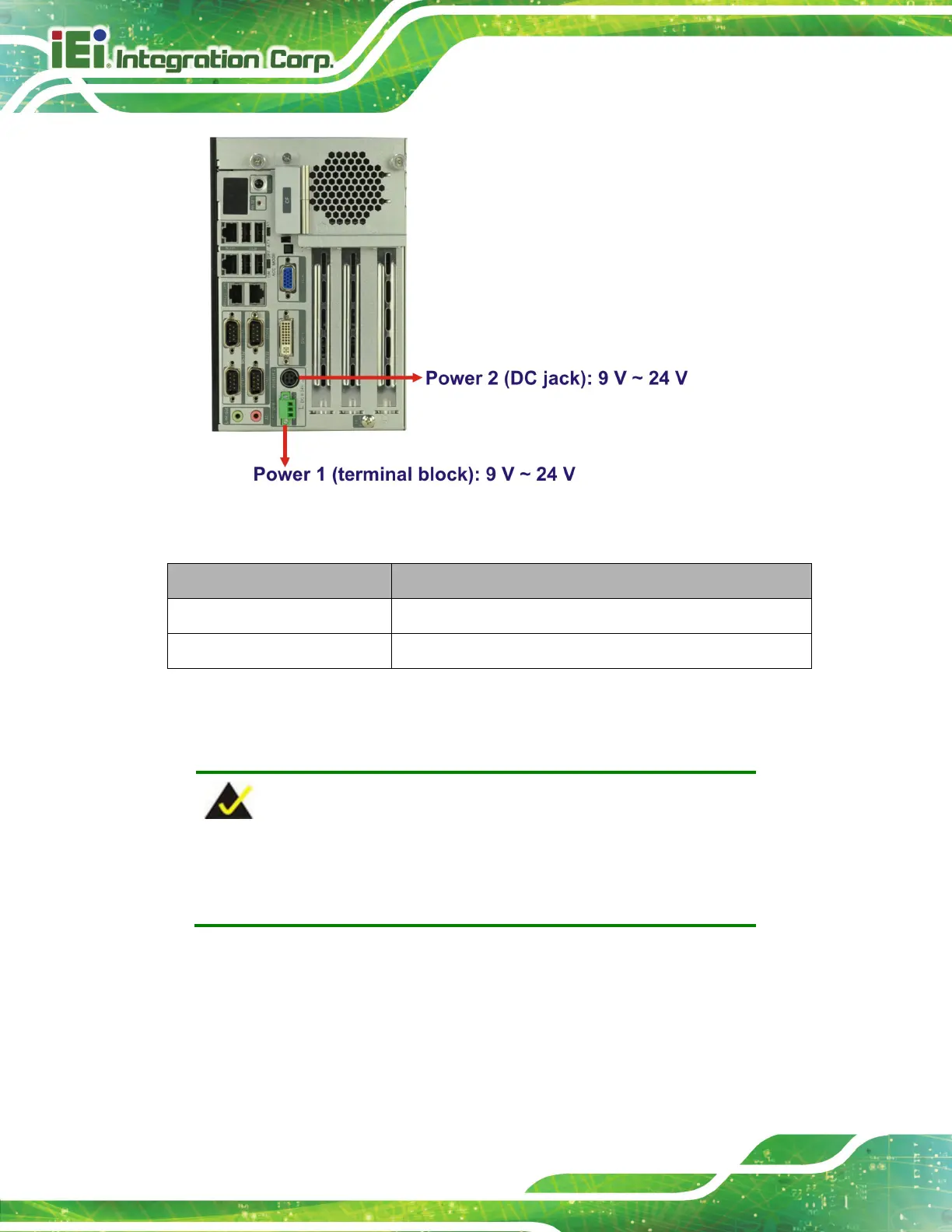
Figure 3-29: Power Connectors
L E D Indic ator Des cription
Power 1
Breathing Orange: Standby mode.
Power 2
Solid blue: Power-on mode.
Table 3-4: Power LED Indicators Description
3.9.1 ACC ON
NOTE:
In ACC On mode, the Power 1 connector must connect to ACC on
signal to be able to control the system power.
The ACC On mode is designed for vehicle applications.
3.9.1.1 Boot-up
When both power connectors are connected to power source with over 9 V power input,
the two power LEDs on the front panel remain off until the ACC ON signal jump from
 Loading...