130 A20733 B0
Input / Output Connections
1 Industrial Interface board
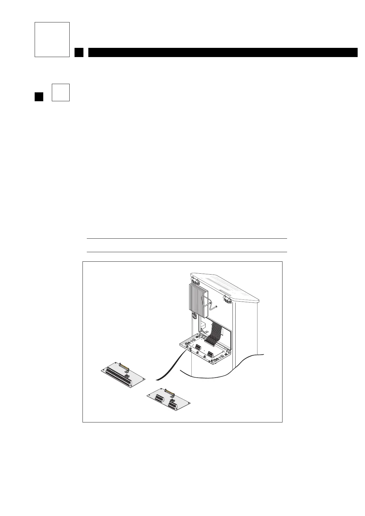
The rear access door must be opened to connect accessories.
To do this:
• Unscrew the two quarter-turn screws located on either side of the rear door.
• Gently pull the door open (see Figure 1).
The connection terminal blocks on the Industrial Interface board are organized as follows:
• Connector B1: 2 x 20 pins CPU signals
• Connector B2: 22 pins Head signals
• Connector B4: 9 pins Alarm relay signals
Details of the pinouts are shown on the following pages.
Figure 1: View of the industrial interface board
OR
Complete board
Simple board