12/53 IMET - M550 ALL1-EN
5.2.2. STOP (E-STOP)
Connect the contact of the E-STOP circuit so that it commands the coil of the machine’s main line
contactor, and remember that the maximum allowable current is 5A.
Attention: The E-STOP circuit has been designed for category 4 UNI EN 954-1 standard and/or
PLe according to the ISO13849-1 standard. In order to keep this safety category, the relays
must be connected in series (pre-cable standard configuration by IMET) or in parallel ONLY to
manage interruption of the main power supply line (See Example 2).
5.2.3. Safety STOP (S-STOP)
The Safety Stop is an additional safety function. It consists in relay inside the receiver monitored by
the RX logic that can be associated with the commands sent by the transmitter and which in case of
problems automatically stops the receiver, as shown by the status LEDs.
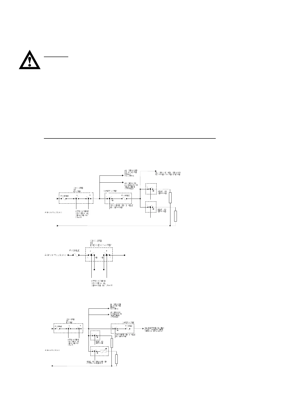
Example 1 (in series to control commands): The Safety Stop introduces a redundancy which activates
the safety function in case the control command relays fail to open.
Example 2 (operating the bypass valve): The Safety Stop can command the drain valve in a hydraulic
machine so that the machine is powered only when a control command is given.
The Safety Stop must not be associated with the bistable selection controls
The risk analysis and safety class are based on Standard UNI EN 954-1 and ISO 13849-1 . The safety
class of each control is shown in Annex B. Take good notice of the maximum currents allowable on
the relay contacts (see Chap. 10).
Example of wiring of Safety-Stop relay for AC applications
Alternative for special applications (for L-AC receivers only)
Example of wiring of Safety-Stop relay for DC applications