IMET - M550 ALL1-EN 11/53
5.2. Connecting the receiver
Do not perform any operation until the equipment is powered off.
The power supply for the radio remote control should be located downstream from the machine’s main
switch.
Connecting to the distribution network directly is prohibited. The network disconnecting
switch foreseen for the distribution network must be equipped with a device protecting from
unauthorised closing (padlock
The connection between the receiving unit and the machine should always be REMOVABLE
. If the
connection is made directly on the terminal board inside the machine, a multipolar connector should
be used so that the receiver can be disconnected and the original wired controls restored at any time.
The wire connections between the receiving unit and the machine should respect Standard EN60204.
The wires must have a cross-section of at least 0.75 mm
2
and must be self-extinguishing.
If possible use ferrules for conductor ends, and make sure that the terminals are fastened tightly.
Consult the transmitting unit controls diagram (Annex A) and the receiving unit wiring diagram to
identify the equivalent actuators in the two units.
Be sure to note the supply voltage when connecting the receiving unit.
In versions H-AC and L-AC, the fuse current must be adjusted to the supply voltage.
After installing, test the radio remote control and the machine to make sure they work as
expected. In addition, it is very important to make sure that the STOP circuit works properly.
Pressing the STOP button during normal operation should make the contacts of relays A and B
in the E-STOP circuit open.
Lastly, fill in the sheet showing the connection diagram between the receiving unit and the machine
and write down the date of installation in the box on page 47 of this manual.
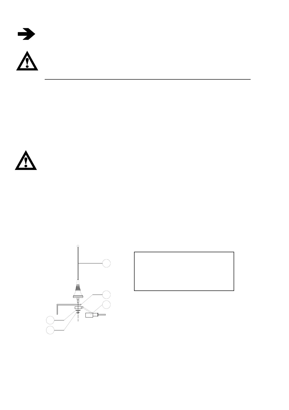
5.2.1. Installing the external antenna
A properly installed antenna is essential for a good operating range. Install the antenna outside at the
highest and most visible point, far from metal structures. Use a tuned antenna only, and connect it to the
receiver using an RG58 coaxial cable (impedance 50Ω). For M550S M8 and M550D M8 type
transmitters only use the antennas supplied by IMET, other types of antenna must be approved in
conformity to the ETSI EN 300 200-2 standard
SYMBOLS
1 Antenna whip
2 Fastening bracket
3 RG58 cable with protective sheath
4 Washer
5 Locking nut
1
2
3
4
5